 We are in Europe
280Z Electronic Fuel Injection
Theory and Troubleshooting
As several components are shared between the 280Z and 280ZX, this document can also be used as a reference for diagnosing and testing certain components of the 280ZX fuel injection system.
In this article
- Section I — Theory of Operation
- Section II — Fuel Injection Troubleshooting
- First Steps
- Troubleshooting — Quick Steps
- Engine Will Not Start
- Engine Hard To Start Only When Cold
- Engine Hard To Start Only When Hot (Above 170°F)
- Engine Starts, Then Stalls
- Engine Idles Too Fast — Cannot Be Adjusted With Speed Screw Or Engine Idle Is Unstable
- Engine Misfires — HC Reading Too High
- Engine Will Not Rev. — Lack Of Power
- Hesitation — Stumble On Acceleration
- Poor Gas Mileage, Or CO Reading Too High
- Surge
- Backfiring
- Afterfire Or Afterburning
- Circuit Testing
- Circuit Testing — 35-Pin Connector Tests
- Component Checks
Section I — Theory of Operation
Although Nissan Motor Co., Ltd. has been installing Electronic Fuel Injection on vehicles sold in Japan for four years, 1975 is the first year for the importation of this system to the United States.
The system used on the new 280Z is similar to the so-called "L-Jetronic" system developed by Bosch in Germany, and employed by various auto manufacturers. It is called "L" Jetronic because it operates on the principle of air flow measurement. The "L" stands for "Luft," which is the German word for "air."
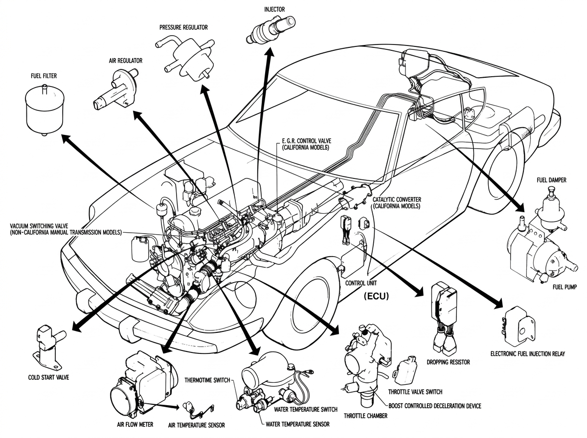
Overview: location of the fuel injection system components on the 280Z
To make it easier to understand the operation of the system, let's break it down into its component subsystems.
The Fuel Circuit

The Fuel Circuit
To make it easier to understand the operation of the system, let's break it down into its component subsystems. Here you can see the Fuel Circuit. Let's take a look at how this circuit works.
Fuel Pump
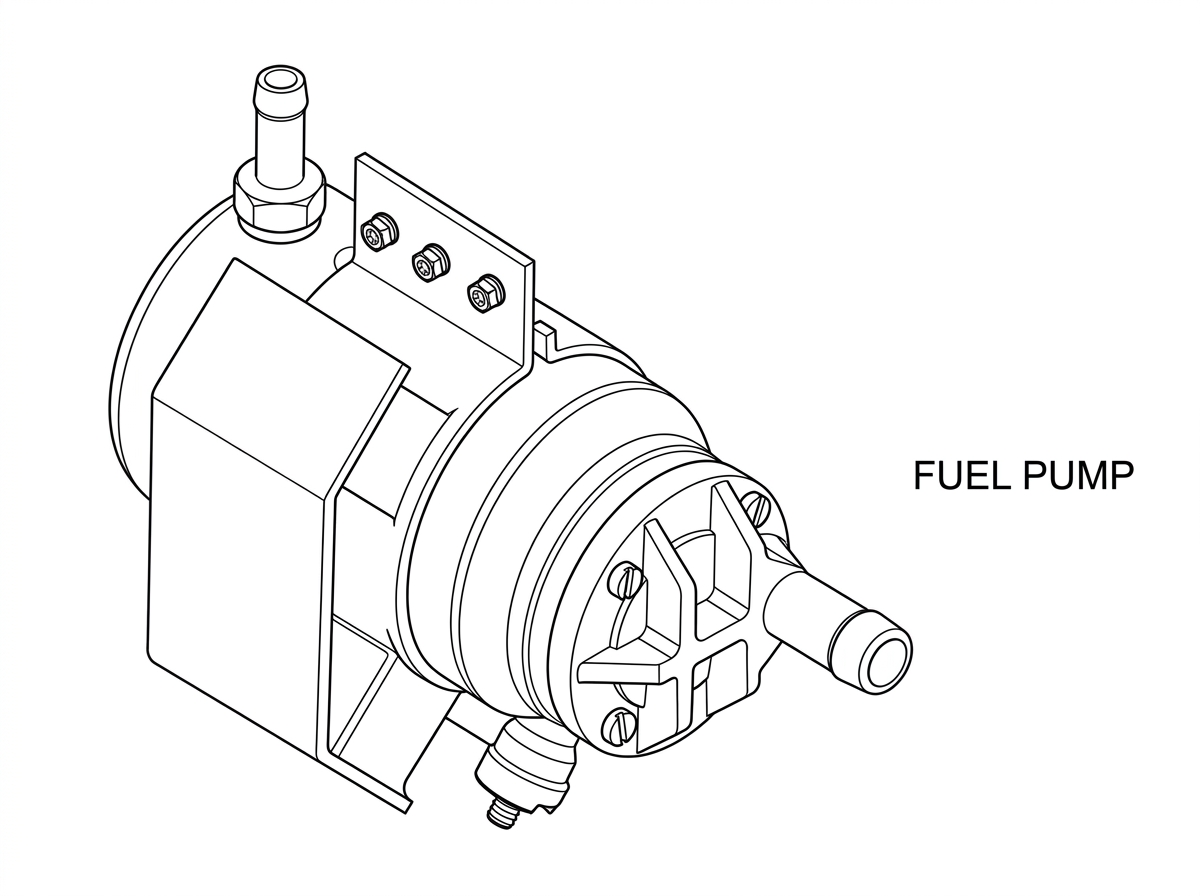
Fuel Pump
First, fuel is drawn from the tank by an electric fuel pump. This is not the same pump as that used on the 1974 Z-Car. This new type is a rotary roller pump in which the armature actually has gasoline flowing around it. For this reason it is called a "wet" type pump.
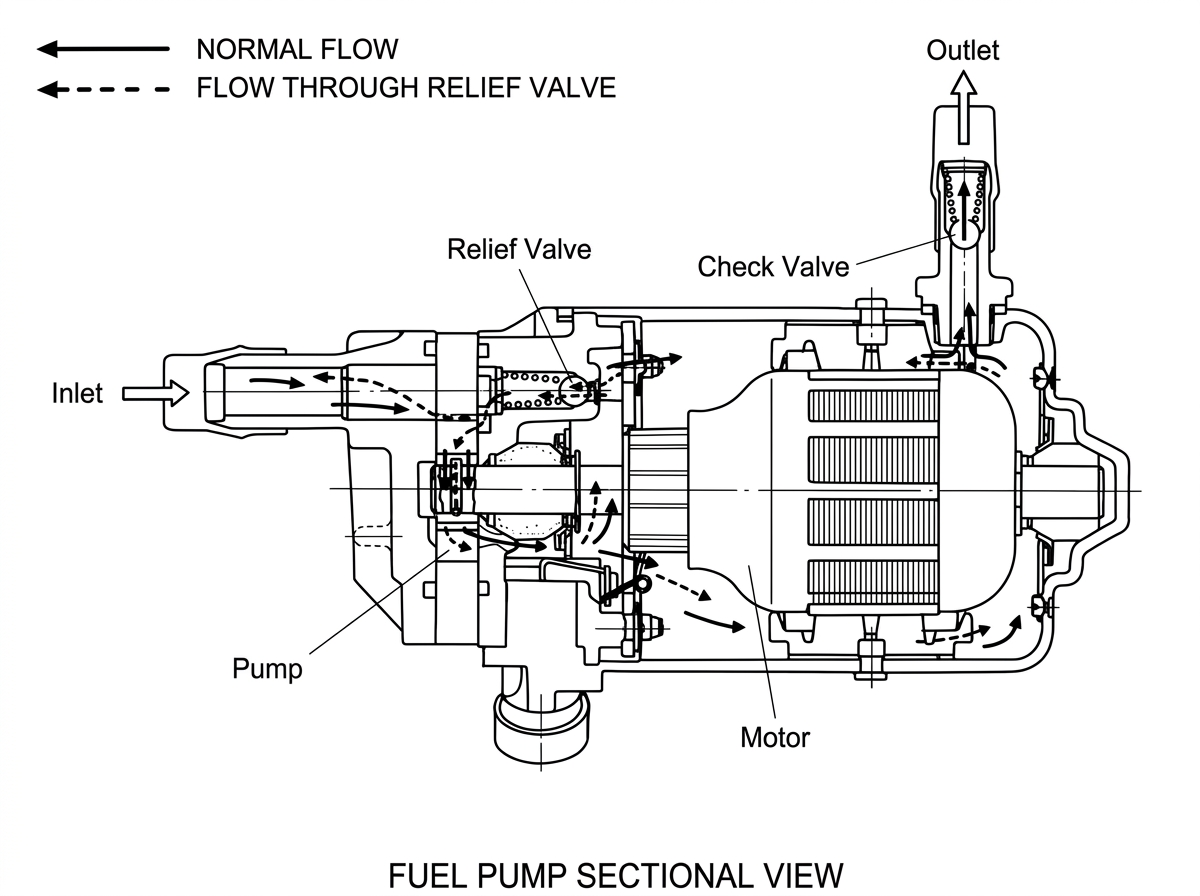
Fuel Pump Sectional View
The fuel pump runs constantly whenever the engine is either running or being cranked. It will not run if the engine stops and if the key is left in the "Ignition On" position.
A word of warning about this pump: DON'T ALLOW THE CAR TO RUN OUT OF GAS, as priming the pump could be very difficult. If the vehicle does run out of gas, you may have to fill the tank all the way to the top before the pump will begin to draw.
The fuel pump also contains a pressure relief valve, which will let fuel recirculate in the pump when pressure goes above 43 pounds psi.
Fuel Damper
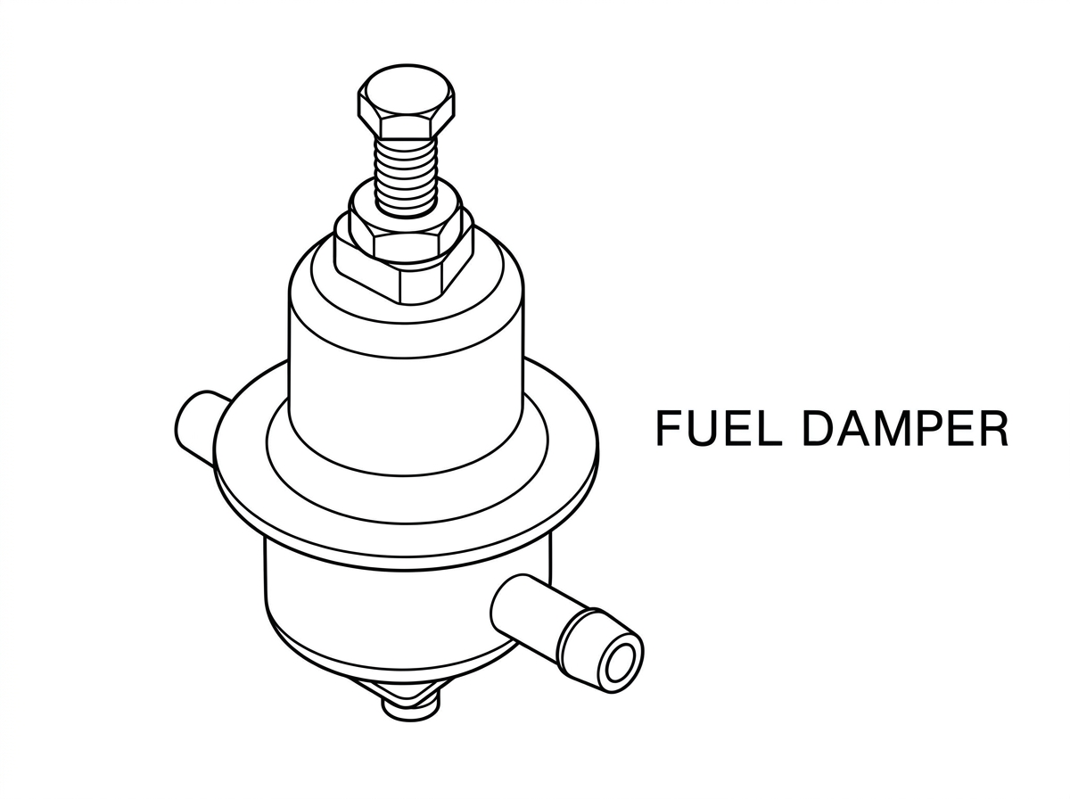
Fuel Damper
From the fuel pump, fuel flows to a fuel "damper," mounted right next to the pump. The damper acts like a shock absorber. It has a diaphragm which is under spring pressure. If the fuel pump puts out pressure surges, then these surges push against the diaphragm and are absorbed by the spring instead of making themselves felt all the way to the injectors, and thus possibly affecting engine performance.
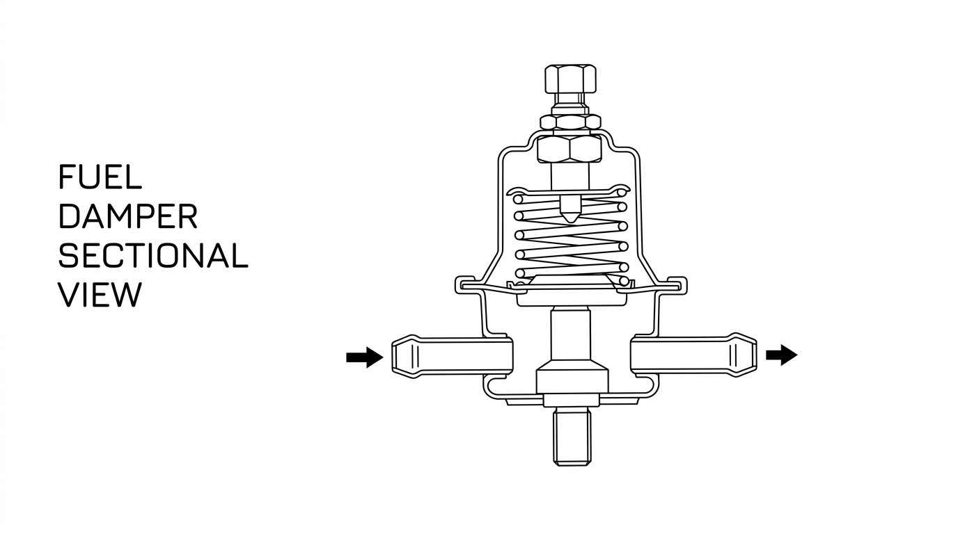
Fuel Damper Sectional View
The fuel damper also acts as a muffler — that is, it keeps the pressure surges from making noises which could be heard by the driver.
Filter
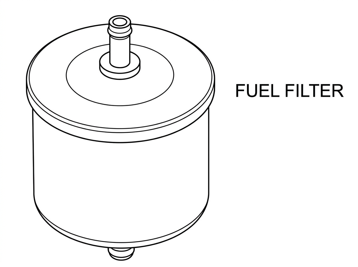
Fuel Filter
From the fuel damper, the fuel passes through the line to the engine compartment where it goes through a special filter, mounted on the right hand fender panel.
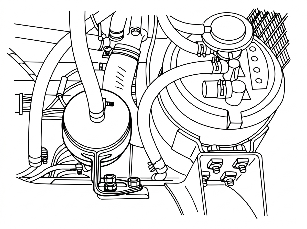
Fuel filter, as mounted on the right hand fender panel
This filter is critical to proper engine operation, since if even the smallest particle becomes wedged in one of the injectors, the operation of that cylinder might be adversely affected. This filter should be changed every 25,000 miles.
Injectors
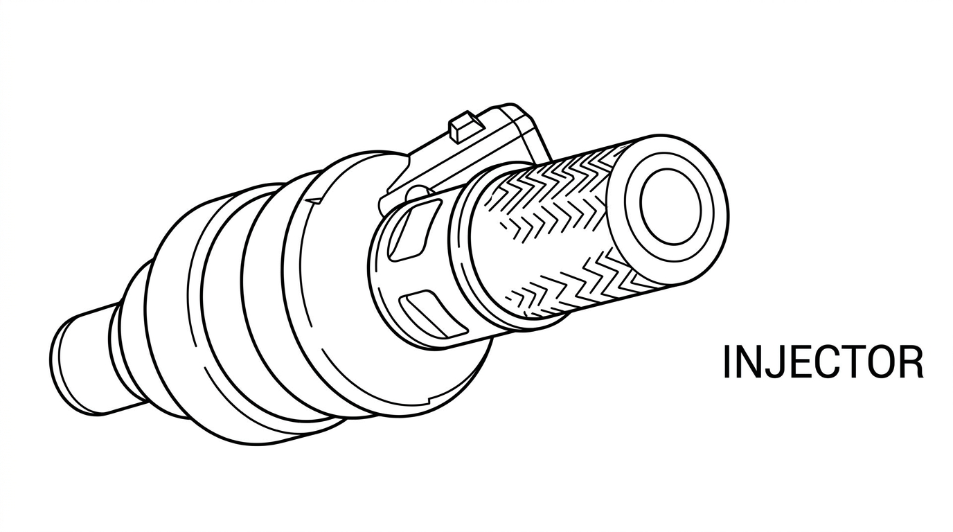
Injector
From the fuel filter, gasoline flows through the line to the injectors. Thus, the injectors have fuel pressure behind them at all times.
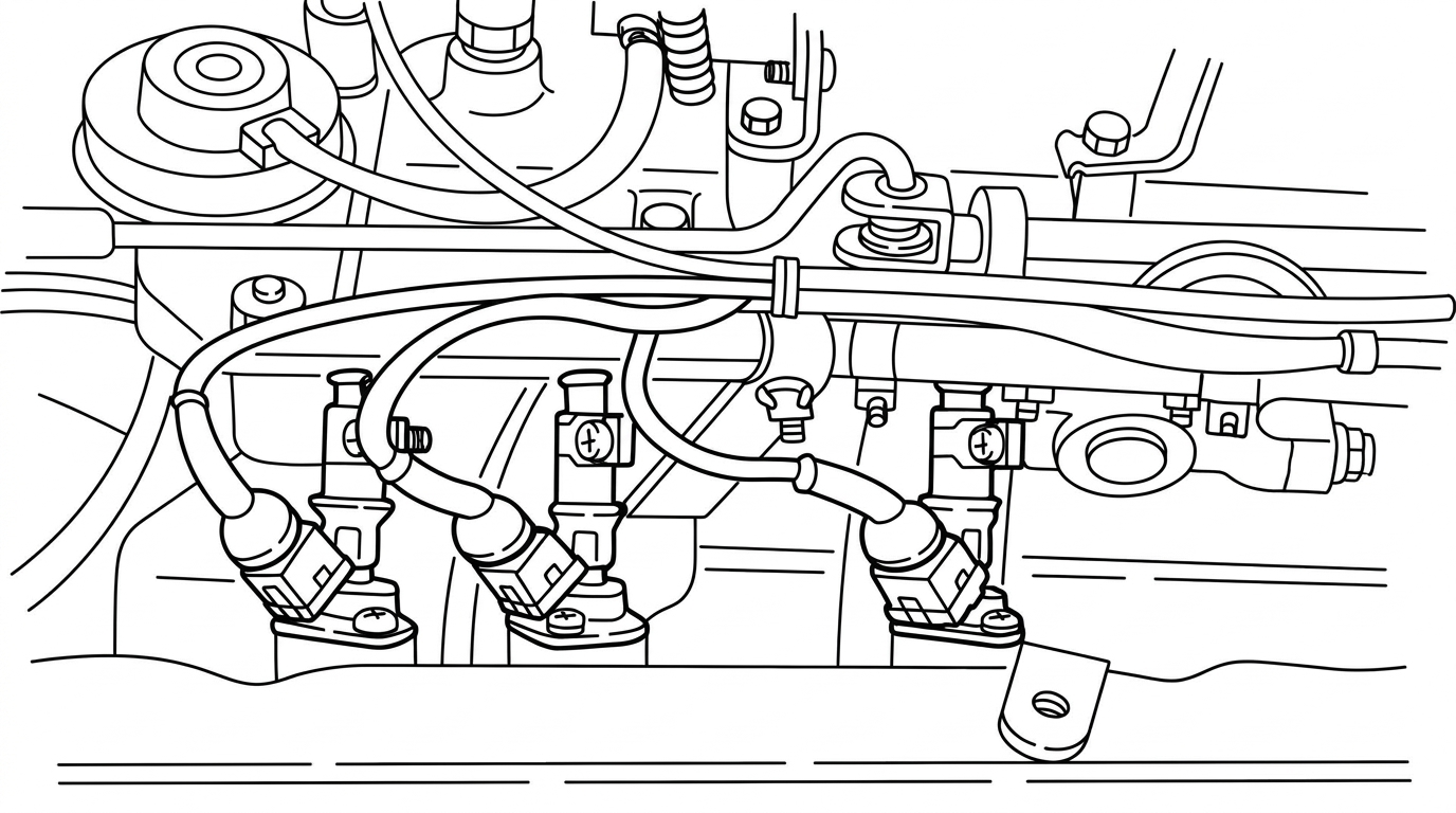
Injectors mounted on the intake manifold, next to the cylinder head intake ports
The injectors are mounted on the intake manifold next to the cylinder head intake ports. (Because of the injectors' location, this type of system is called manifold injection.)
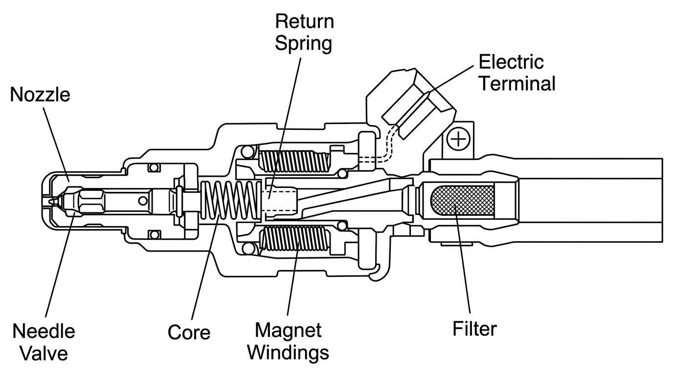
Injector cutaway, showing the nozzle, needle valve, core, magnet windings, return spring and filter
The injectors are really little magnet valves. When they are energized, they open; gasoline is then squirted into the intake manifold. The longer they stay open, the more gasoline will be injected, and the richer the system will run.
Injector Operation
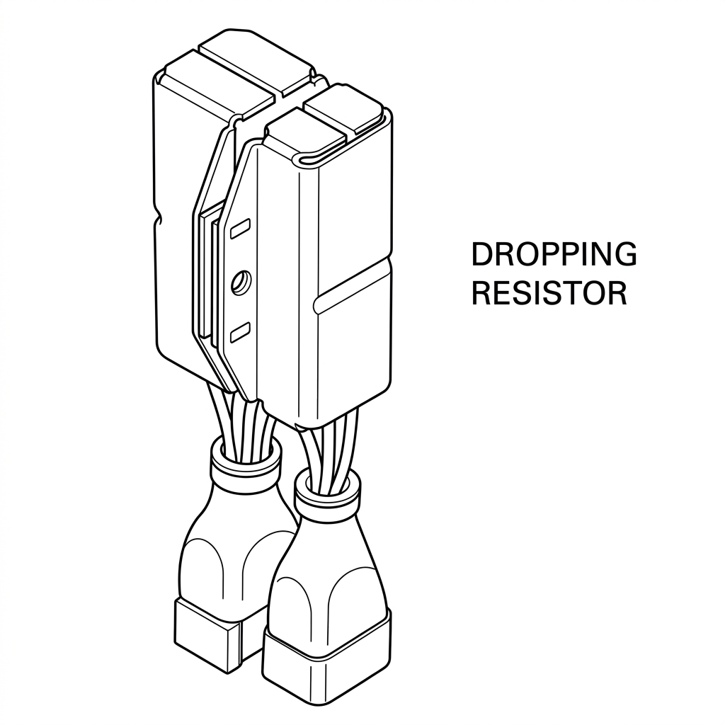
Dropping Resistor
When the system is operating, the battery is connected directly to each injector through a resistor. Thus there are six resistors on the 280Z. The resistor causes a voltage drop so that the injector operates on less than battery voltage.
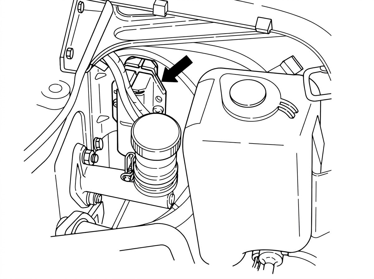
Dropping resistor location
The resistor also protects the injector from voltage surges coming from the alternator and from the effects of other components in the electrical system.
Control Unit
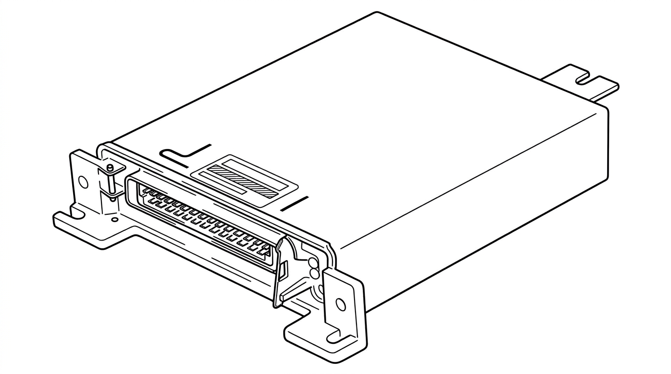
Control Unit
The injectors are grounded inside the Electronic Control Unit, or ECU. This unit controls the injectors by turning their ground on and off, just the way the transistor ignition control unit turns the coil ground on and off.
When the control unit grounds the injectors, current runs from the battery, through the resistor, through the injector and then finally into the control unit. Since the circuit is complete, the injector is energized. It opens and gasoline is injected into the manifold.
This is the basic principle of fuel injection operation. The control unit can govern how much fuel is injected by holding the injectors open for longer or shorter periods of time.
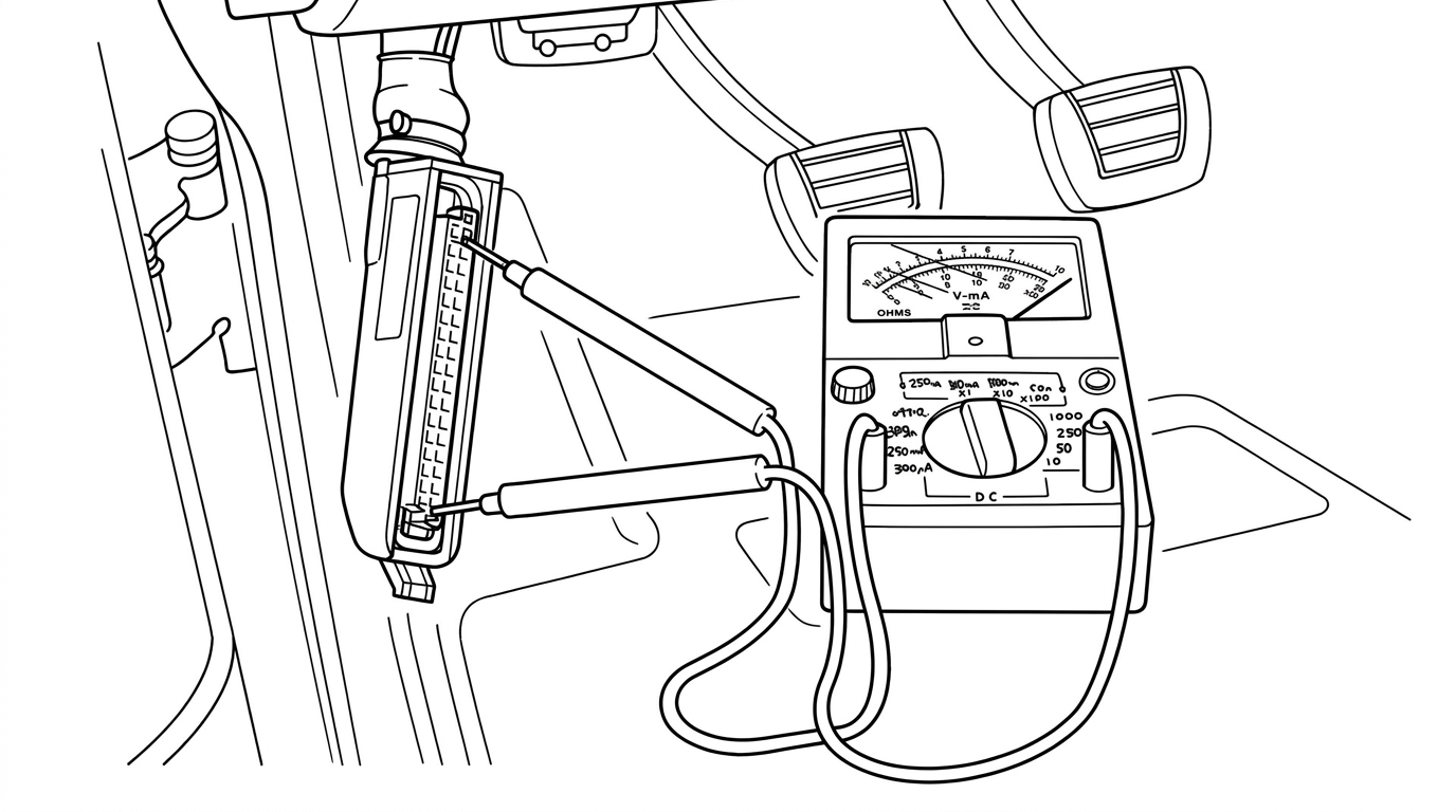
Testing at the ECU connector, on the driver's side kick panel
The ECU is mounted on the driver's side kick panel behind a protective cover. By the way, the large connector at this unit can be used to test the entire Fuel Injection System.
Pressure Regulator
Note: the page also carries the subheading "Fuel Pressure Regulation" ahead of the Pressure Regulator heading below; both are reproduced here as printed.
Obviously, the pressure of the fuel going to the injectors is very important. If the pressure goes up, more fuel will be injected during a certain period of time. If the pressure goes down, then less fuel will be injected. There is also the effect of manifold vacuum: if the vacuum gets very high, more fuel will be "sucked" out of the injectors; while if the vacuum drops, less fuel will pass through them.
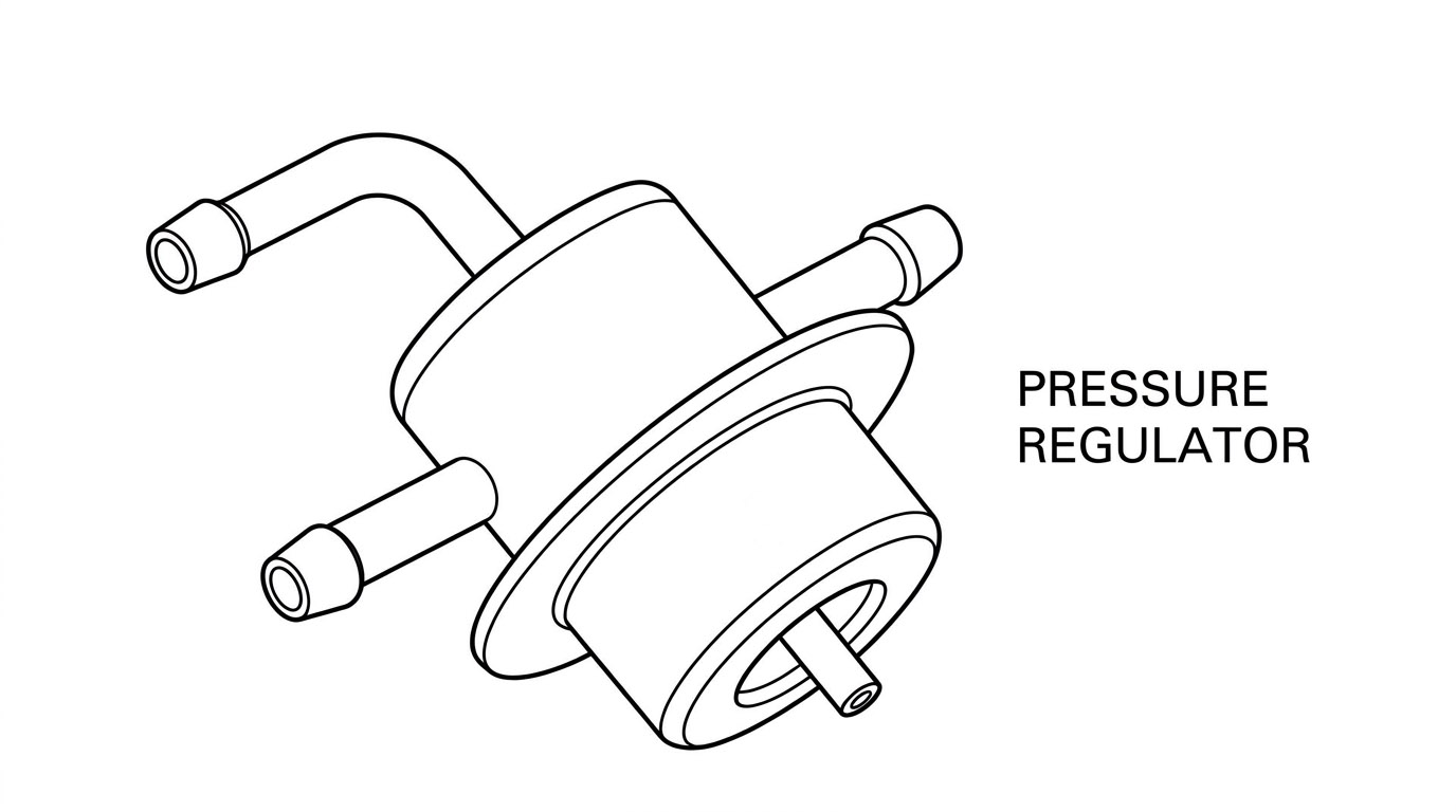
Pressure Regulator
Therefore, the system includes a fuel pressure regulator. When the pressure in the line gets too high, then this pressure regulator opens and allows some fuel to flow back to the fuel tank by the return line. When the engine is running, there is actually a constant bleed of gasoline back to the fuel tank.
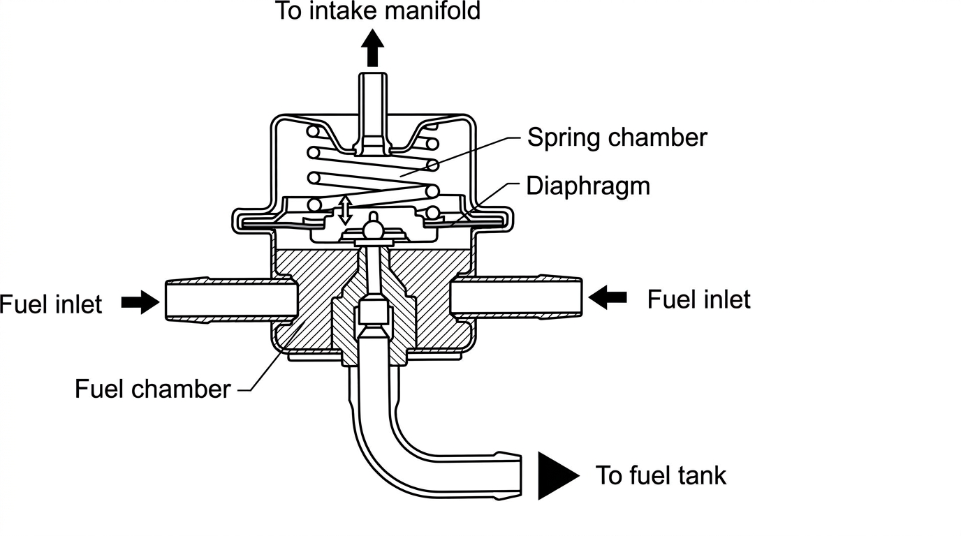
Pressure regulator cutaway, showing the spring chamber, diaphragm and fuel chamber
A vacuum sensing line, connected to the intake manifold, allows the manifold vacuum to operate against the pressure regulator diaphragm. As vacuum goes up, the regulator thus allows more fuel to bleed back to the tank, and so the fuel pressure lowers. The pressure regulator thus maintains a constant balance between fuel and manifold pressure, keeping the difference between them at 36 pounds psi.
The pressure regulator is pre-set and cannot be adjusted.
Fuel Injection Air Flow
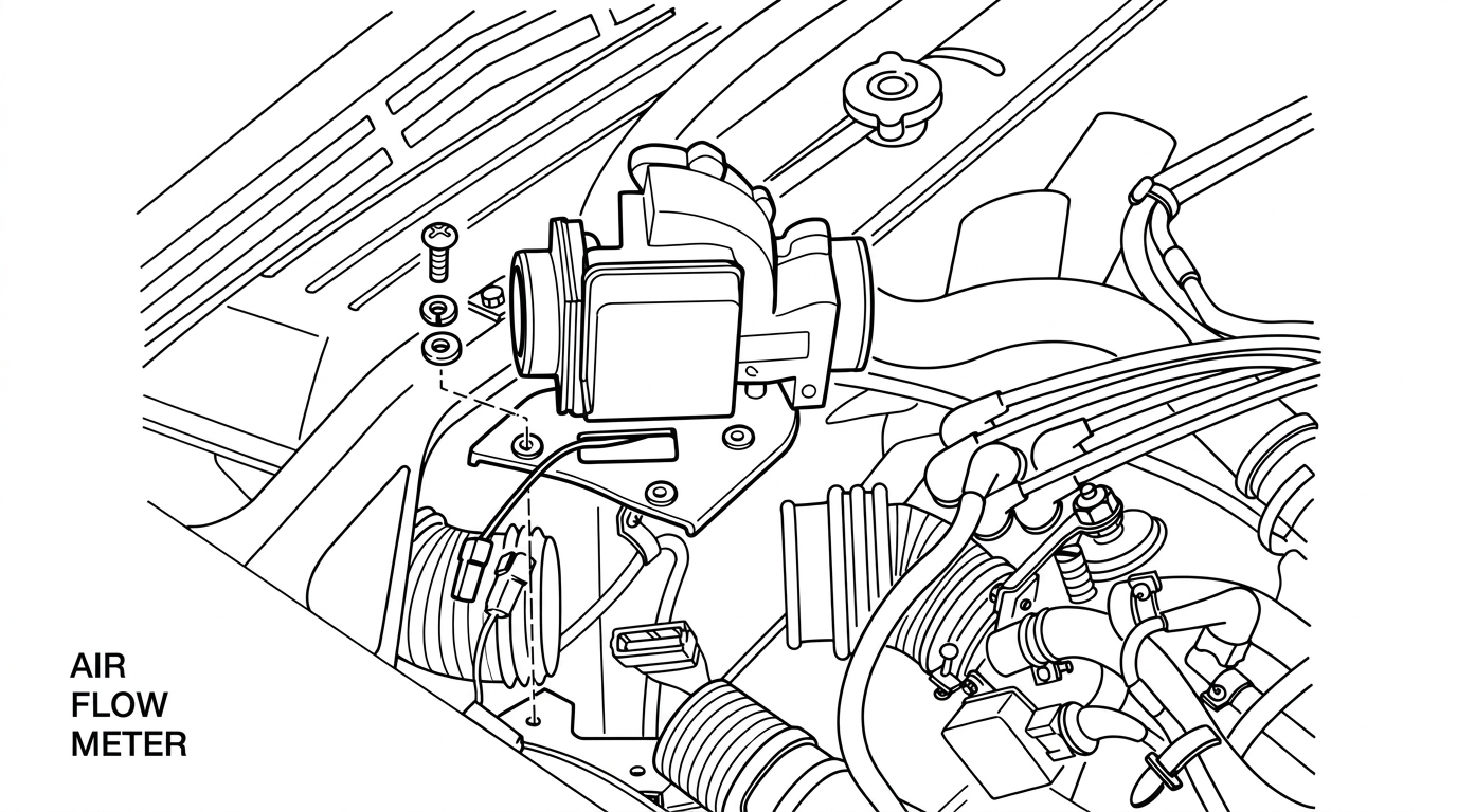
Air Flow Meter, mounted between the air cleaner and the throttle plate
How does the Control Unit know how much gasoline should be injected? The main source of information is the Air Flow Meter, which is mounted between the air cleaner and the throttle plate. This meter measures the amount of air coming into the intake manifold, in much the same manner as the gas tank gauge measures the amount of fuel in the tank.
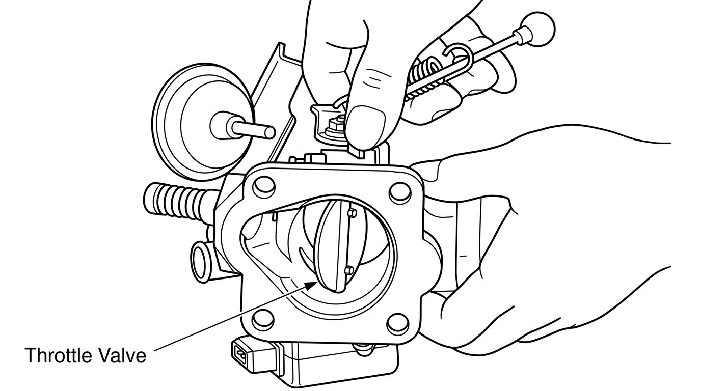
Throttle Valve
Just as with a carbureted engine, the speed of the engine is determined by the throttle. When the throttle is opened, air passes through the air filter and into the air flow meter.
Air Flow Meter
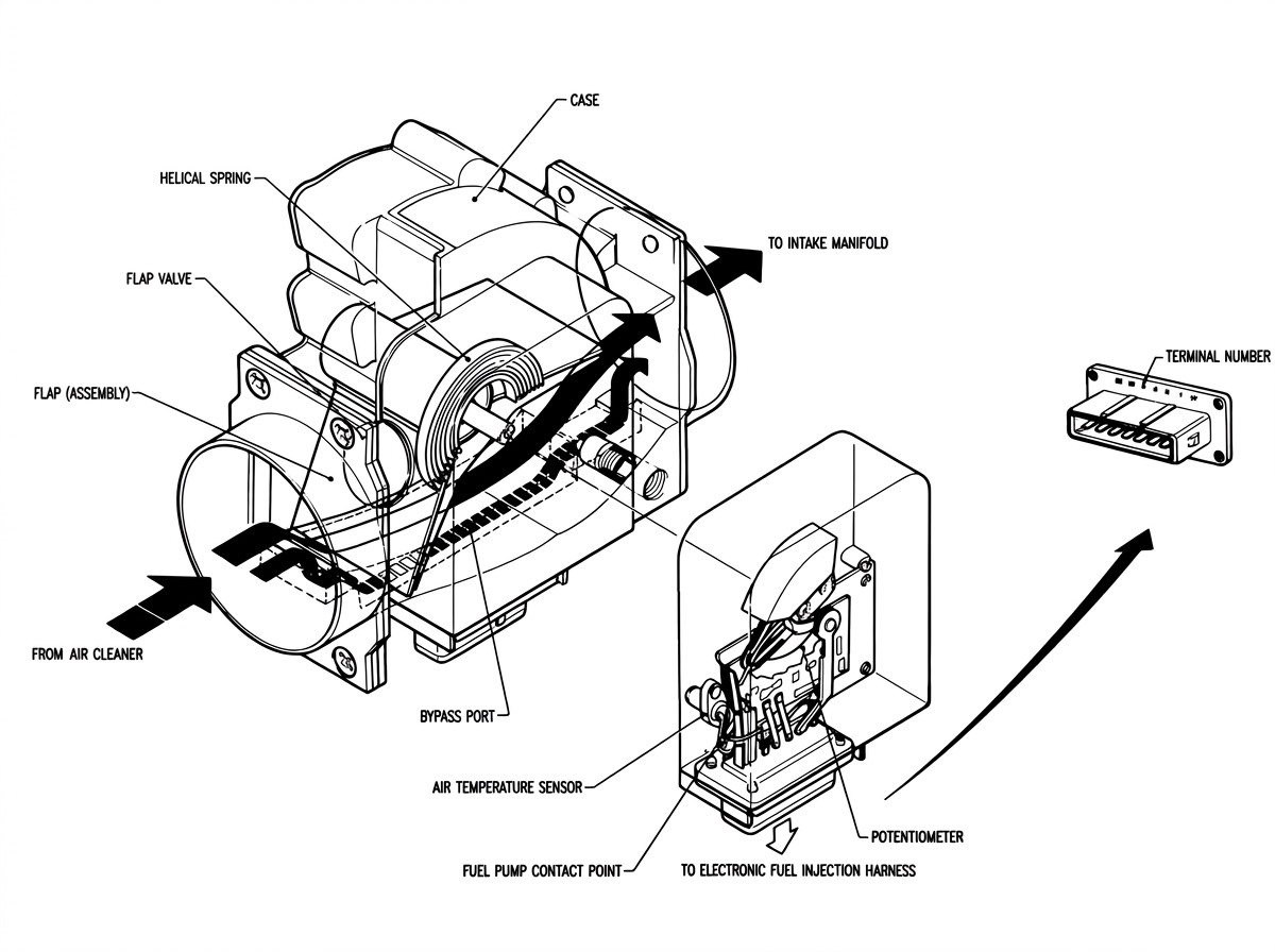
Air Flow Meter (exploded view)
In order to pass through the meter, the air must push open a hinged flap. The more air passing through, the farther the flap will be pushed open. The air will then pass by the throttle plate and travel on into the cylinders.
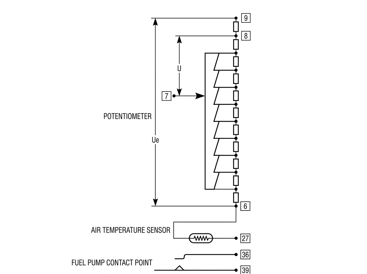
Potentiometer, air temperature sensor and fuel pump contact point circuit
The air flow meter is connected to the control unit, and sends a voltage signal to it. The farther the flap is pushed open, the stronger the signal which the air flow meter supplies to the control unit. The control unit then responds by holding the injectors open longer so they inject more fuel. Thus the air flow meter is the control unit's most important source of information which it uses to judge the fuel-air ratio. The control unit, the injectors, and the air flow meter form the heart of the fuel-injection system.
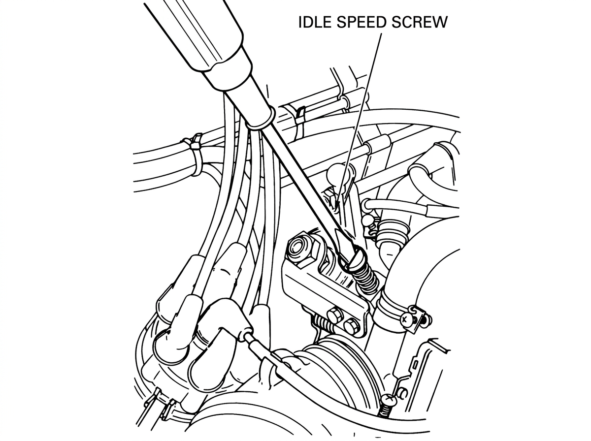
Idle Speed Screw
What happens at idle? When the throttle is closed, air passes through an idle bypass, the size of which is controlled by an idle speed adjusting screw.
Air also flows through a bypass in the air flow meter. (This bypass is installed so that air flow into the engine at idle can be uniform. You see, if all the air had to go past the flap, individual piston pulsations at the low idle speed would cause the flap to shudder, and an uneven fuel mix would result. This idle bypass is factory set and cannot be adjusted.)
As you can see, the air flow in our injection system is even easier to understand than was the fuel flow. There is one point, however, which is very IMPORTANT: ANY VACUUM LEAK AT ALL, from the air flow meter to the intake valve, WILL CAUSE THE IDLE SPEED AND AIR-FUEL MIXTURE RATIO TO CHANGE, since this leaking air will not be measured by the air flow meter.
Sensor Inputs to the Control Unit
So far, we have looked at how the fuel and air actually reach the engine. We have also looked at the air flow meter, which is the principal source of input to the control unit.
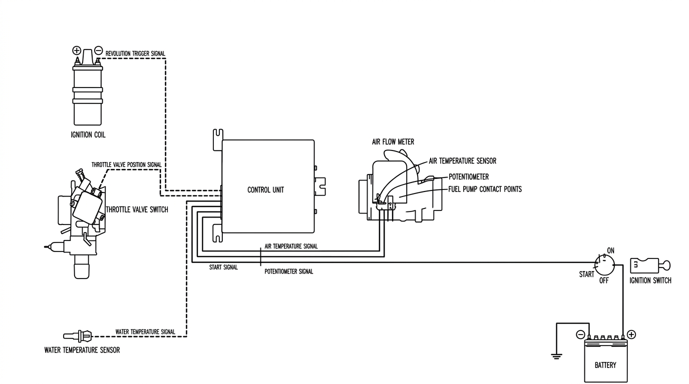
Electronic Fuel Injection System (Electronic Signal)
Actually, though, there are a total of six inputs to the control unit which all work together to determine the final mixture ratio. Let's take a look at the other five sensor inputs.
Coil
First, there is the ignition coil, which tells the control unit how fast the engine is turning. In other words, this is a tachometer hookup. The control unit can vary the mixture ratio with speed, since engine requirements change from idle to very high RPM. Also, this connection to the negative side of the coil tells the unit when the cylinders are firing, and therefore it serves to time the moment of injection. The control unit fires all the injectors at the same time, once per revolution (twice per cycle).
Throttle Switch
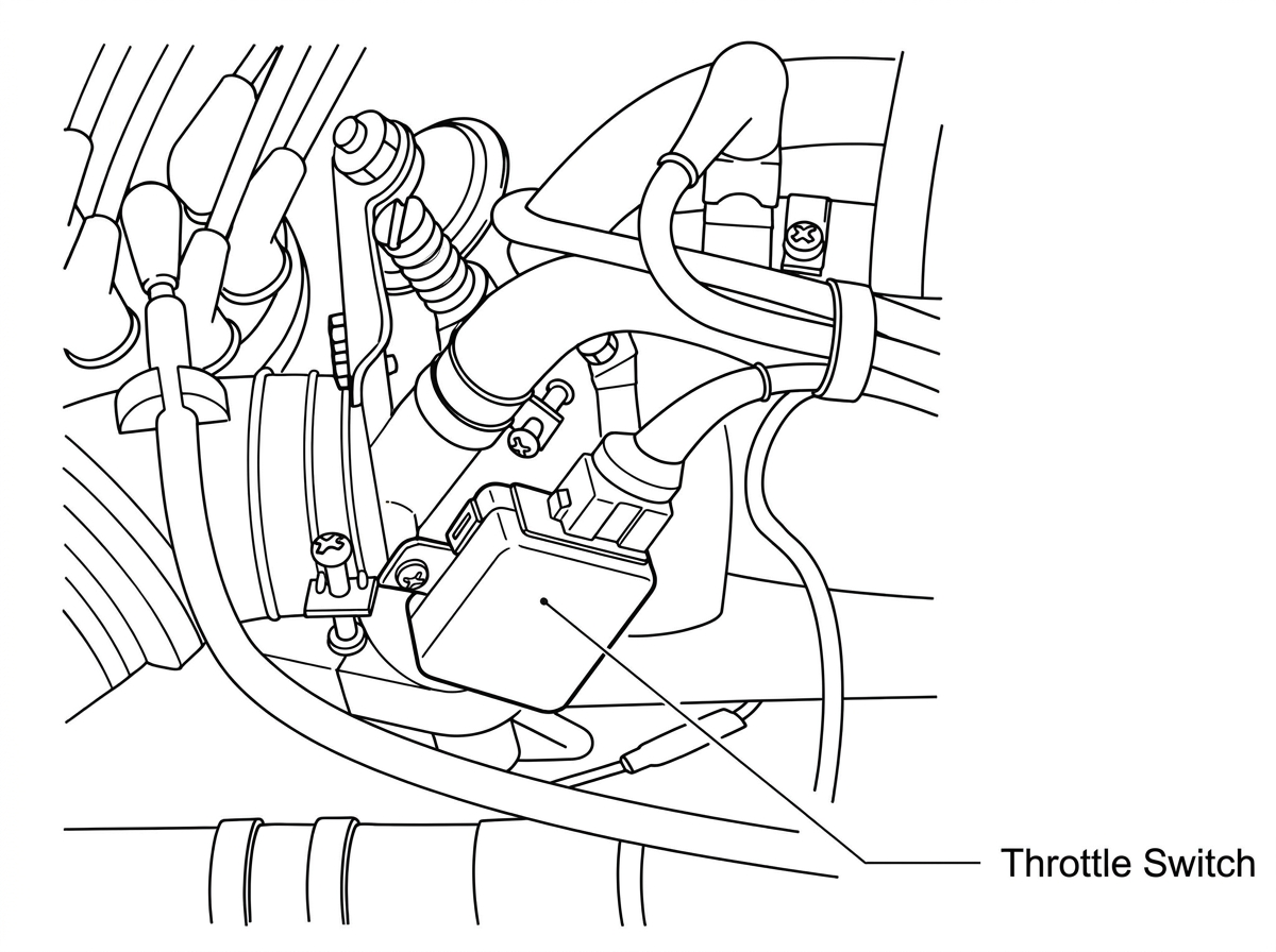
Throttle Switch
The next sensor input comes from a switch which is mounted on the throttle chamber, and which is therefore called the throttle switch. This sensor actually contains two separate switches, and supplies two different signals to the control unit.
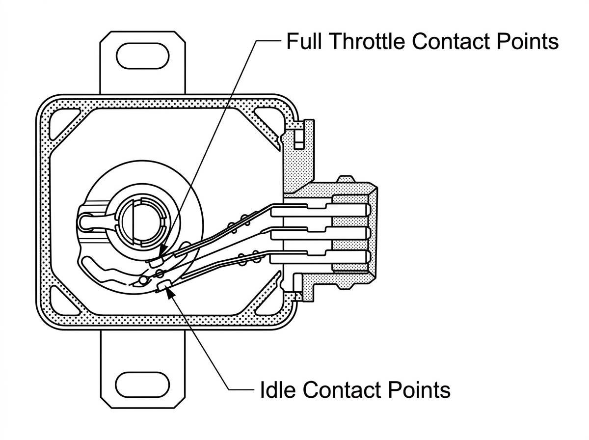
Throttle switch interior, showing the Full Throttle Contact Points and Idle Contact Points
The first of these is the idle switch, which is closed when the driver releases the throttle. This tells the control unit that the engine is either idling or decelerating. You can see that the ignition coil input tells the control unit which is the case. If the engine is idling, then the control unit can richen the mixture ratio slightly, just as the idle circuit in a carburetor supplies a slightly richer mixture than does the high-speed circuit.
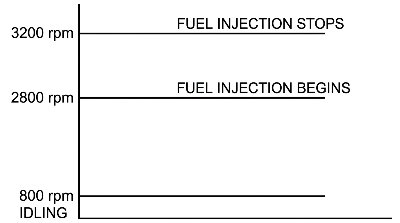
Fuel injection cutoff and resumption speeds during deceleration
If the engine is decelerating, on the other hand, then less gas is needed; in fact, from any speed above 3200 RPM down to 2800 RPM, the control unit turns off the gas completely. Thus we can get better gas mileage and fewer emissions.
The throttle switch also contains another set of contacts, called the full throttle contacts. These are closed when the driver opens the throttle past a certain point. The control unit can respond by richening the mixture — again, according to engine speed. Thus we can obtain both acceleration and heavy load enrichment.
Water Temperature Sensor
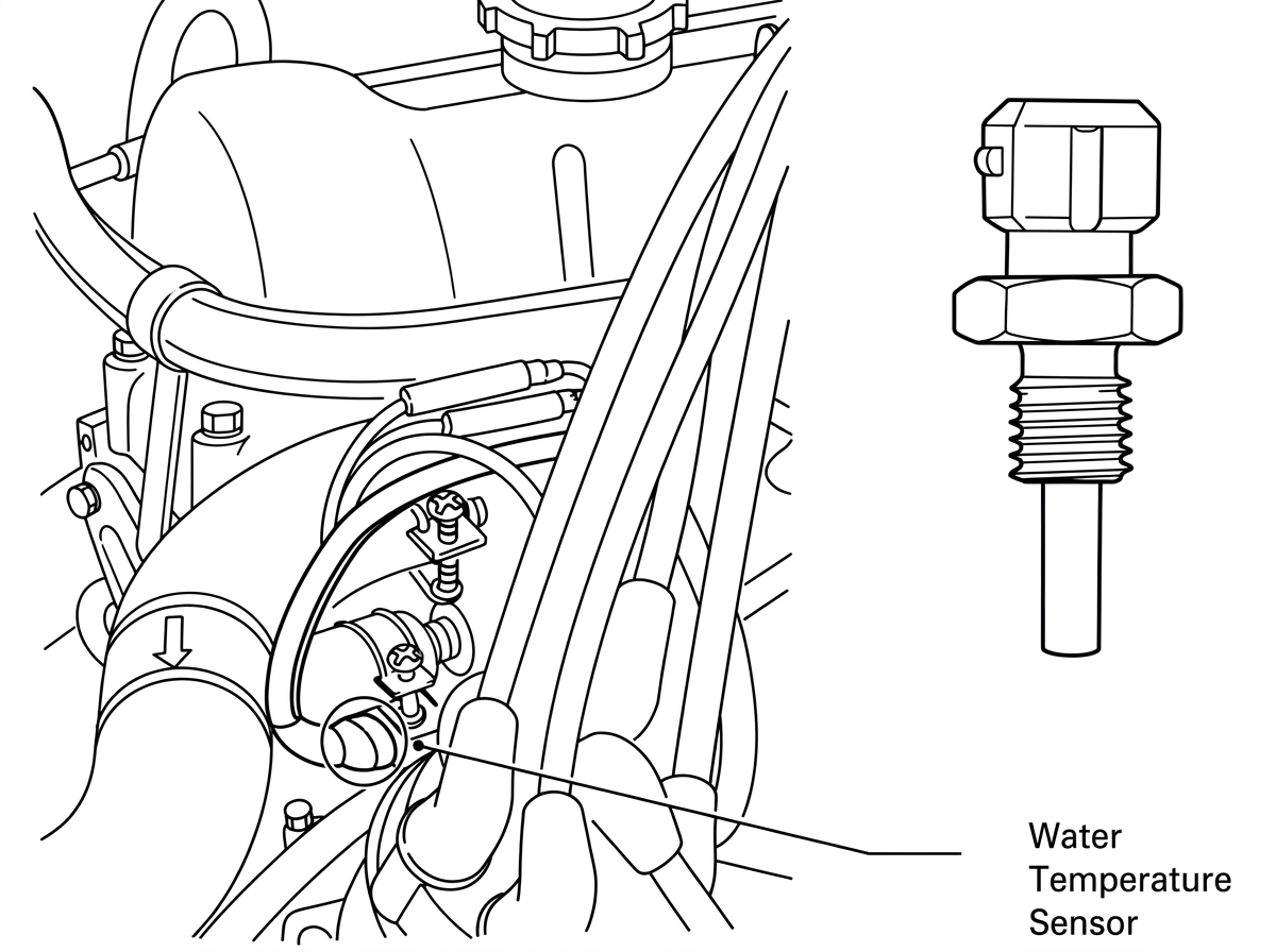
Water Temperature Sensor
Next, a water temperature sensor, located in the thermostat housing, allows the control unit to richen the mixture until the engine arrives at operating temperature. While the engine is warming up, the oil is thicker; there is more resistance, so more fuel is needed.
This sensor is just like the sensor which controls the water temperature gauge in the dash. That is, it changes its resistance as the engine temperature changes. The warmer the engine, the leaner the mixture, until the water temperature reaches 150 degrees Fahrenheit. (After warmup, this sensor should not affect injection operation.)
Air Temperature Sensor
When the intake air is colder, it is denser. Or, in other words, there are more molecules (particles) of air in a given space. Therefore, more fuel must be mixed with this cold air than would be necessary with hot air.
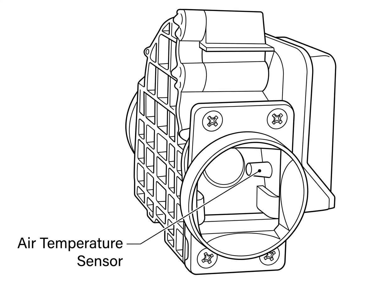
Air Temperature Sensor
An air temperature sensor measures the temperature of the air coming in from the air cleaner. While the air is warming up to 68 degrees, additional fuel is metered to the cylinders by the control unit. This temperature sensor works like the water temperature sensor; so the colder the intake air, the richer the mixture. Thus it is not necessary to preheat the air using vacuum motors and breather preheating tubes as are used on our carbureted engines.
Start Signal
The control unit also receives a signal from the ignition switch while the engine is being cranked. This is because an engine requires additional fuel while starting since additional power is needed to move from a standstill to idling RPM, and because the air velocity through the manifold is not sufficient to cause a complete mixture of fuel and air. The control unit therefore responds to the start signal by holding the injectors open longer during cranking.
Summary
Here again are the six sensor inputs to the control unit:
- Air Flow Meter
- Ignition Coil
- Throttle Switch (2 positions)
- Water Temperature Sensor
- Air Temperature Sensor
- Ignition Switch Start Signal
Cold Start System
Just like a carbureted engine, the fuel-injected Z-Car needs a choke system which supplies very large amounts of fuel only during starting. Also, like a carbureted engine, we need a fast idle to raise the engine speed while the engine is warming up.
Cold Start Valve
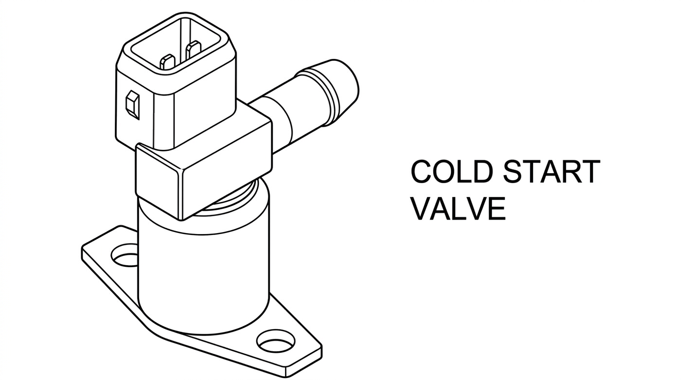
Cold Start Valve
To inject the additional fuel, we use a cold start valve. This is actually a seventh injector, and is mounted behind the throttle plate where it can spray fuel into the air which is going to all the cylinders. When you crank the engine, current goes from the ignition switch to this valve, which is then energized and sprays a very fine mist of fuel into the manifold. When you release the key, the current to this valve is cut off. This is very important to remember: THE COLD START VALVE GETS CURRENT ONLY WHEN THE STARTER IS CRANKING.
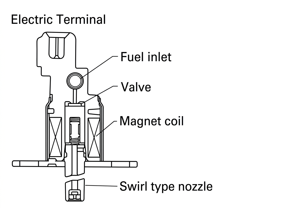
Sectional View of Cold Start Valve
Now suppose the engine is in need of new spark plugs, and the ignition system is therefore not firing as well as it should. You would have to crank the starter longer before the engine would start. You can see that if the cold start valve continued to stay open, the engine might flood.
Thermotime Switch
This problem is avoided by grounding the cold start valve through a switch with a little heating element in it. When the starter is being cranked, current runs from the ignition switch through the cold start valve to this switch and thus to ground. While this is happening, the little heater in the switch is operating; and after a certain time, the heat causes the switch (bimetal) to open.
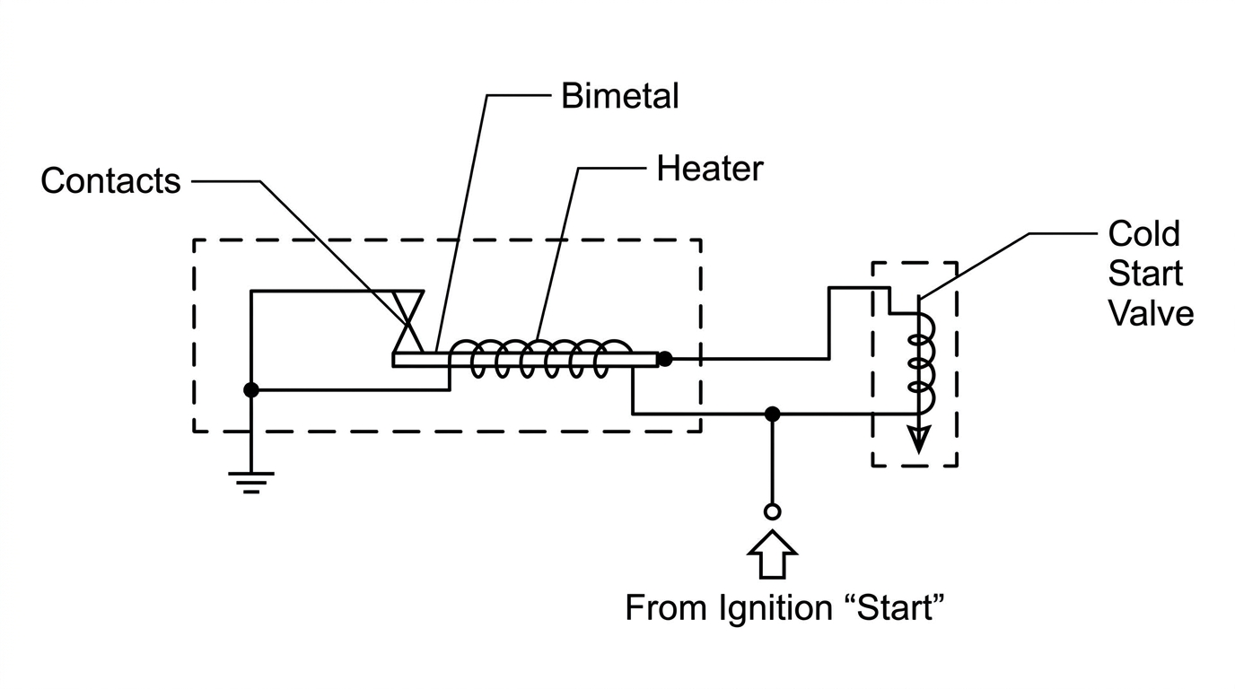
Cold Start Valve — Thermotime Switch Schematic
Because this switch operates according to both temperature and time, we call it the Thermotime Switch.
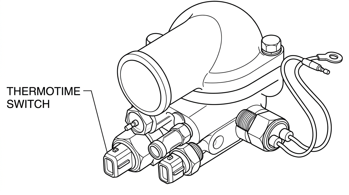
Thermotime Switch
This switch is screwed into the thermostat housing next to the water temperature sensor. This is because a cold engine will need the cold start valve operation for a longer period of time than will a warm engine; and a hot engine will not need the valve at all. So, the engine heat also acts on the switch and makes it turn off the cold start valve. Therefore, the length of time that the cold start valve operates depends directly on engine temperature. (Incidentally, the maximum time for valve operation is about 12 seconds.)
Auxiliary Air Regulator
As we mentioned before, we also need some form of "fast idle" system to supply additional air during warmup.
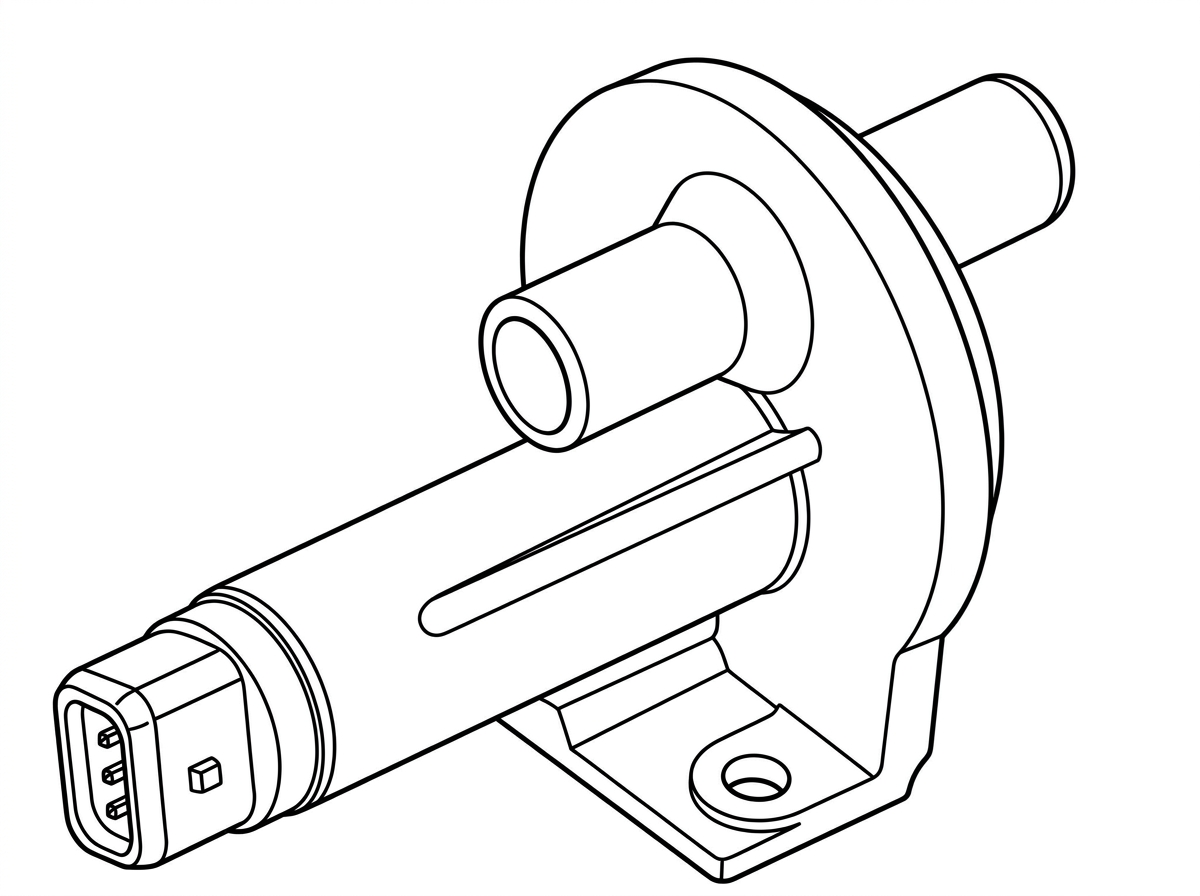
Air Regulator
With fuel injection, this is easy to do. You know that idle speed can be raised by simply by-passing the throttle plate. During warmup, we do exactly that by using an air valve, called an Auxiliary Air Regulator. This valve is similar to the electric automatic choke used on our carbureted engines. That is, it contains a heating element. Let's look at how this valve operates.
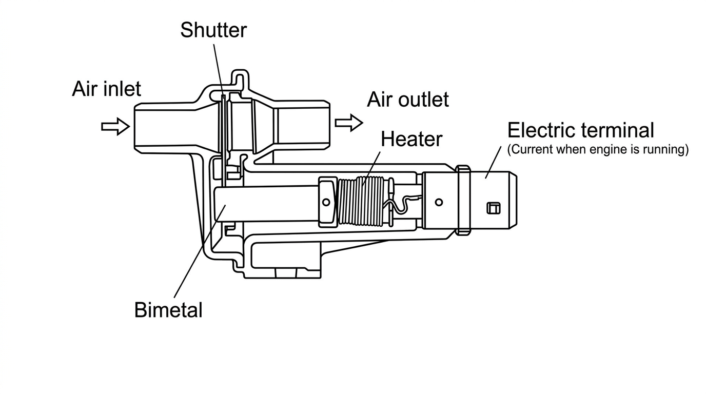
Sectional View of Air Regulator
When the engine is cold, the valve is open; so when the engine starts, air can bypass the throttle plate and go through the valve. Now as long as the engine is running, current is supplied from the battery to the heating element in the valve. As the element heats up, a bimetal causes the valve to close slowly, closing off the air passage. Thus, the engine idle speed is progressively lowered.
Note: This valve is not controlled electrically by either the Cold Start Valve or to the Control Unit.
Fuel Injection Electrical System

Fuel injection system complete wiring diagram
Harness
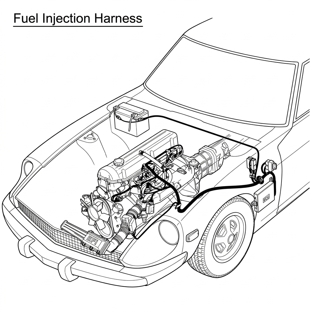
Fuel Injection Harness
On the 280Z, the wiring harness for the fuel injection system is completely separate from the other electrical circuitry in the vehicle. This makes troubleshooting easier. The harness also employs special plugs which lock securely in place, thus minimizing the possibility of poor connections.
All of the circuits in the system can be traced using the large 35-pin connector at the control unit. (See Troubleshooting Section.)
Injection Relay
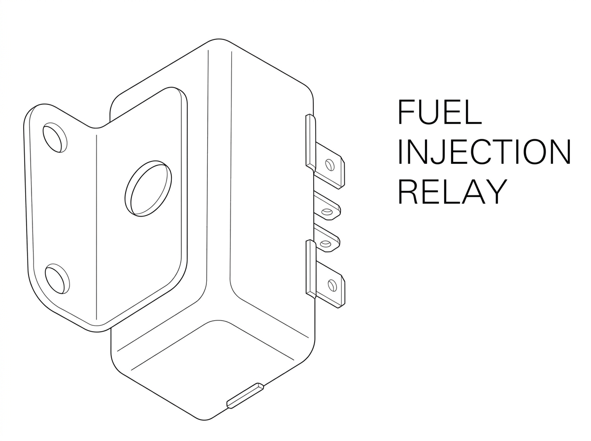
Fuel Injection Relay
The heart of the electrical system is the Fuel Injection Relay, which sends current to everything from the control unit to the fuel pump to the injectors. This is mounted on the left hand kick panel, above the control unit.
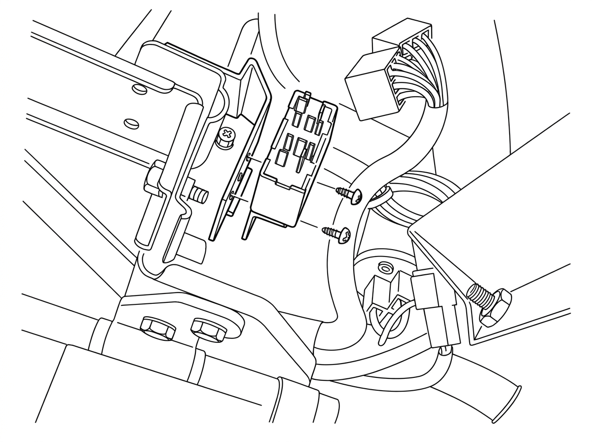
Fuel injection relay, mounted above the control unit
The fuel injection relay is really two relays in one. Let's take a look at them and at what they do.
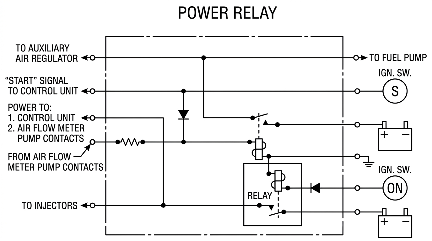
Power Relay
The first part of the relay acts as a power relay. This is the main power source for the injection system. It sends current from the battery to the control unit, so that the unit can then operate all of its sensors and its own internal circuits.
This power relay also sends current to the fuel injectors. As you know, the current goes first to the injector resistors, and then to the injectors.
Finally, the power relay also sends current to a special set of contacts in the air flow meter. We'll look more closely at these contacts in a moment.
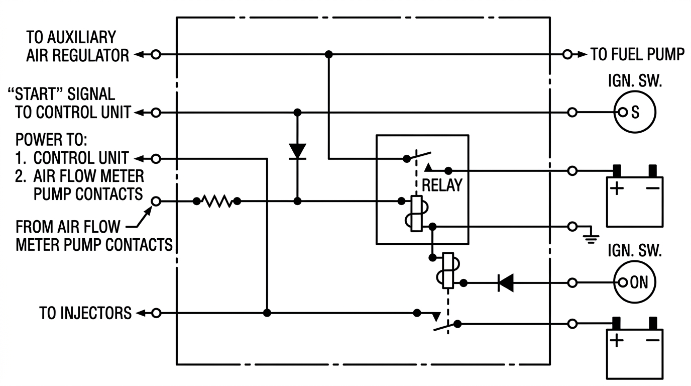
Fuel Pump Relay
The other section of the fuel injection relay is the Fuel Pump Relay. This relay sends current from the battery to the fuel pump. At the same time, it energizes the heating element in the Auxiliary Air Regulator.
Relay Operation
Both of these relays are controlled by the ignition switch. Let's take a look at how they work.
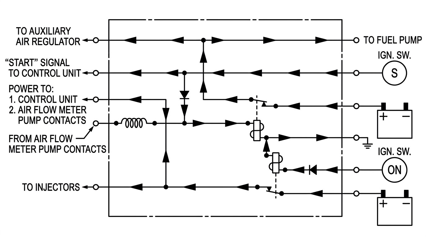
Fuel Injection Relay (Start Position)
When the ignition key is turned to the "start" position, both relays are energized directly. That is, the power relay is energized, and current runs to the control unit, to the injectors, and to the air flow meter contacts. At the same time, current also runs to the fuel pump relay, which in turn sends battery current to the fuel pump and to the Auxiliary Air Regulator.
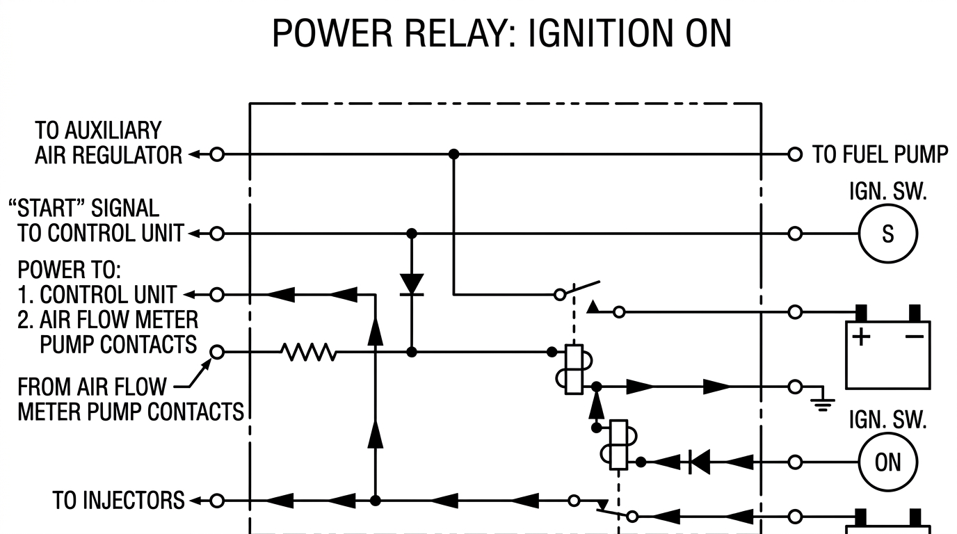
Power Relay: Ignition On
Now when we release the key, current continues to run to the power relay, which remains energized. So the control unit, injectors, and air flow meter contacts continue to receive current.
The fuel pump relay, however, no longer receives current directly from the ignition switch once it reaches the "on" position. That means that the fuel pump and the auxiliary air regulator are not automatically energized when the key is in this position.
There are two reasons for this: (1) Suppose the vehicle is in an accident where the engine is stopped and a fuel line has been damaged? If the fuel pump were allowed to continue running because the key was "on," then fuel might spray all over, creating a fire hazard. Therefore, we must see to it that the fuel pump stops when the engine stops; (2) Suppose you start the car on a cold day, and then go inside the house while the engine warms up — if the engine dies, and the auxiliary air regulator continues to receive current from the ignition switch, then there will no longer be a fast idle. The engine would then be difficult to start. The air regulator must therefore stop working when the engine stops.
Thus the fuel pump relay is energized (in the ignition "on" position) only when the engine is running. How is this managed?
Air Flow Meter Contacts
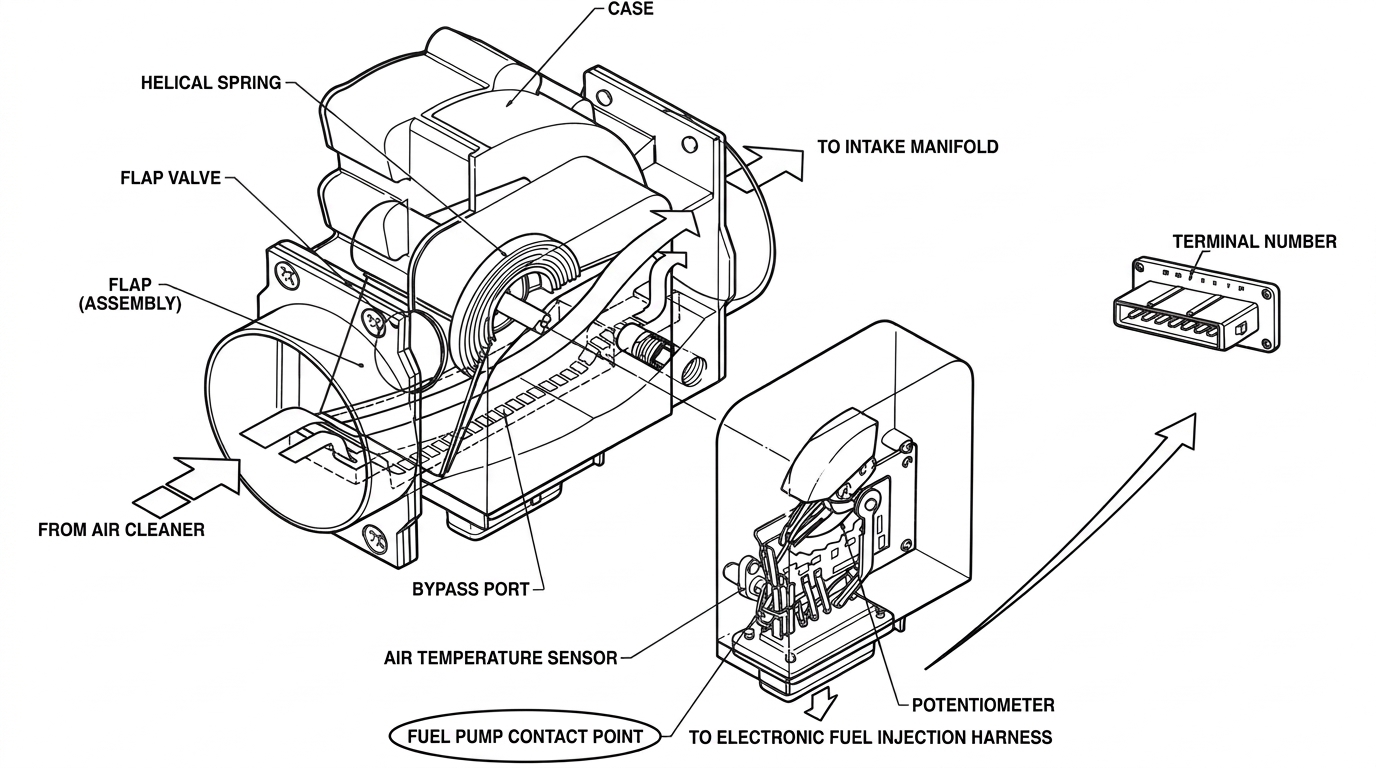
Air Flow Meter Contacts
In order to sense when the engine is running, the engineers have installed a special fuel pump switch in the air flow meter. As soon as the engine starts, the air flow through the meter pushes the flap far enough to close the switch contacts.
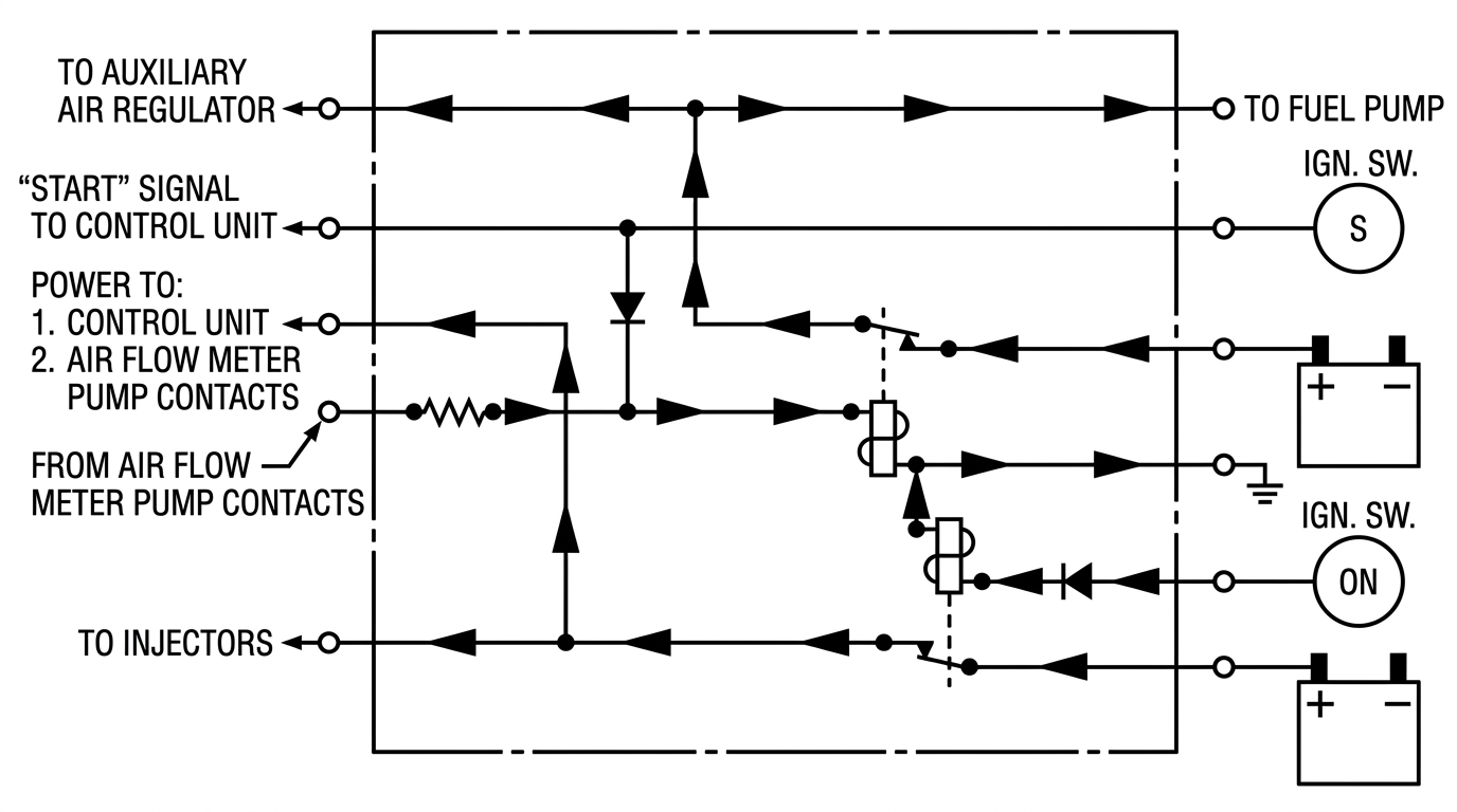
Fuel Pump Relay: Engine Running
Now current flows from the power relay, through the contacts, and back into the fuel pump relay. The fuel pump relay is therefore activated, and sends current to work the fuel pump and the auxiliary air regulator. If the engine stops, then the air flow will stop. The fuel pump contacts in the meter will open, the relay will disengage, and the fuel pump will stop working.
By the way, the diode in the fuel pump relay keeps current from feeding back toward the starter when the relay is working.
A thorough understanding of these basic principles is invaluable to fuel injection troubleshooting. Most important is an understanding of the wiring diagrams which you will find in the 280Z Service Manual, pages EF-25 - EF-50.
So that's all there is to the new Fuel Injection System. What at first might appear to be difficult, is really very simple when it is broken down into its component parts.
The next section of this book describes detailed testing and troubleshooting which can be performed using basic test equipment.
Section II — Fuel Injection Troubleshooting
First Steps
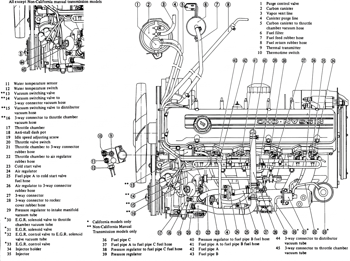
Underhood vacuum-hose and fuel-injection component locator diagram (all engines except non-California manual-transmission models shown separately, inset lower left)
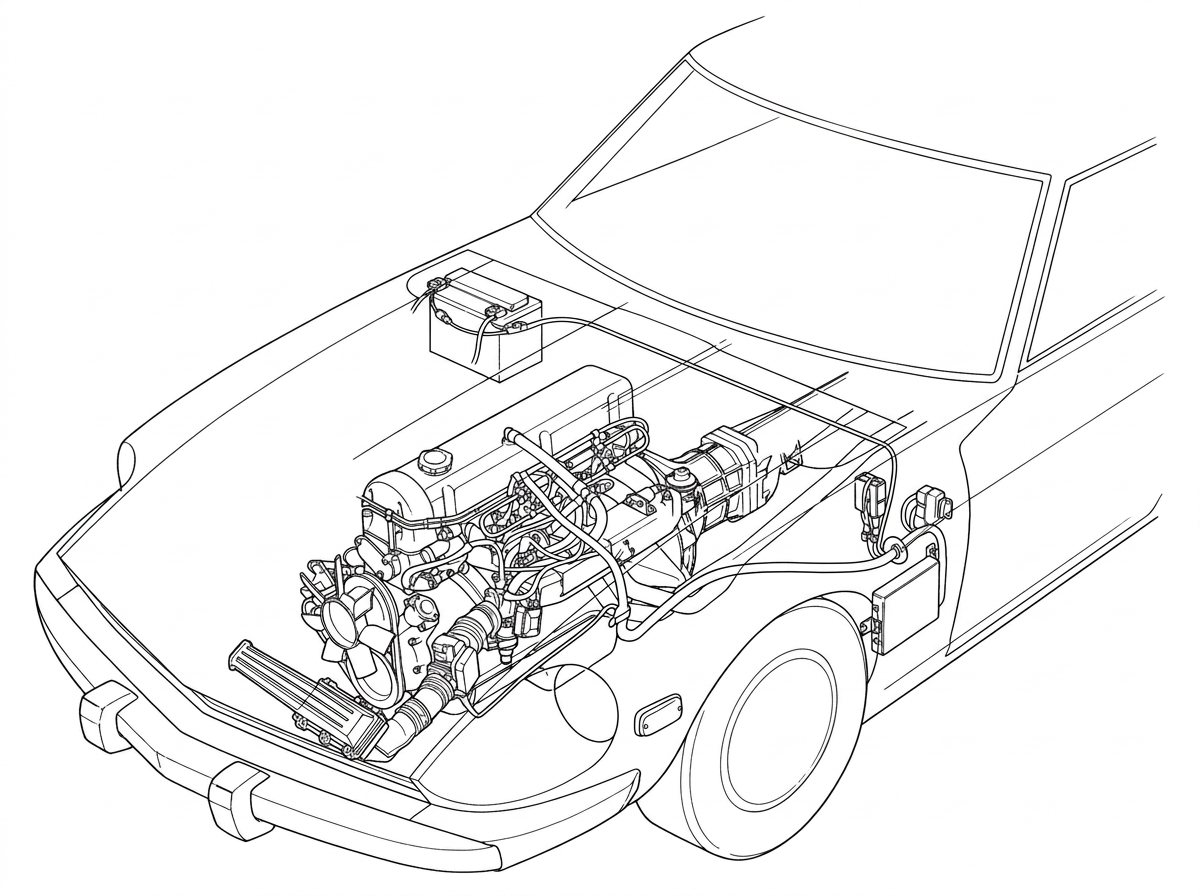
280Z engine bay with the fuel injection wiring harness (bold line) traced from the battery to the control unit
- The greatest problem source with a system of this type lies in the connections between components. Save time by performing a quick check of all connectors for (a) looseness and (b) corrosion. Pull all connectors off and reconnect after inspecting terminals.
-
Next, make sure all hoses are in good condition. Check for cracks or vacuum leaks.
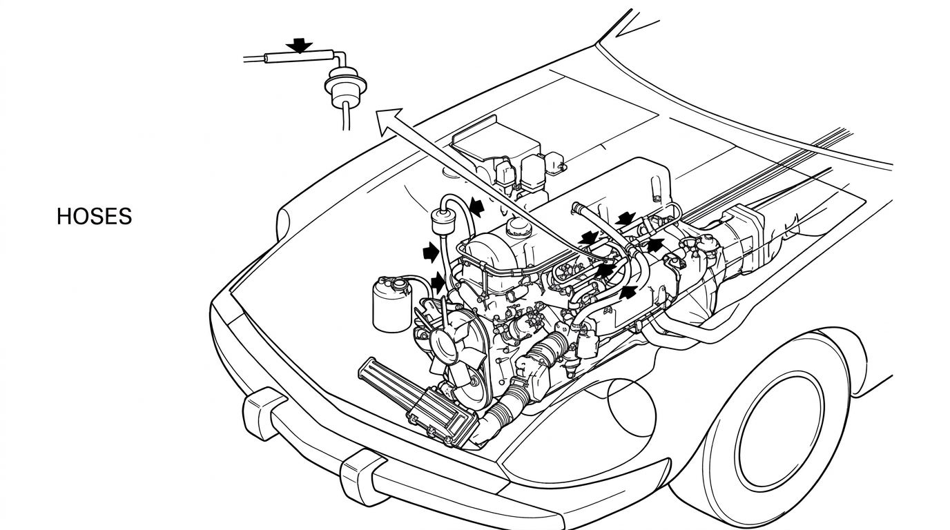
Checking hose connections in the engine bay for cracks or leaks
- Finally, make sure the (a) ignition and (b) starting systems are satisfactory. Battery voltage should not drop below 9.6 volts while cranking.
Troubleshooting — Quick Steps
The manual's quick-reference index for this section lists the following symptoms and their manual page numbers: Starting Problems — Engine Will Not Start (p. 32), Hard To Start When Cold (p. 34), Hard To Start When Hot (p. 35), Engine Starts, Then Stalls (p. 36); Idling Problems — Idle Too High Or Too Rough (p. 38); Misfiring - HC Too High (p. 39); Lack Of Power Or Engine Will Not Rev. (p. 40); Hesitation - Stumble (p. 41); Poor Gas Mileage (p. 42); CO Too High (p. 42); Surge (p. 43); Backfire (p. 44); Afterfire (p. 44); Circuit Tests - Using The Control Unit 35-Pin Connector (p. 45); Component Checks (p. 72).
Engine Will Not Start
- Check The Ignition System:
- Scope
- Pull Coil Wire Out Of Distributor And Check For Hot Spark
- Check For Vacuum Leaks (See Diagram On Previous Page)
- PCV Valve, Dip Stick Seal, Oil Filler Cap Seal
- Air Flow Meter Hoses And Clamps
- Manifold Gaskets
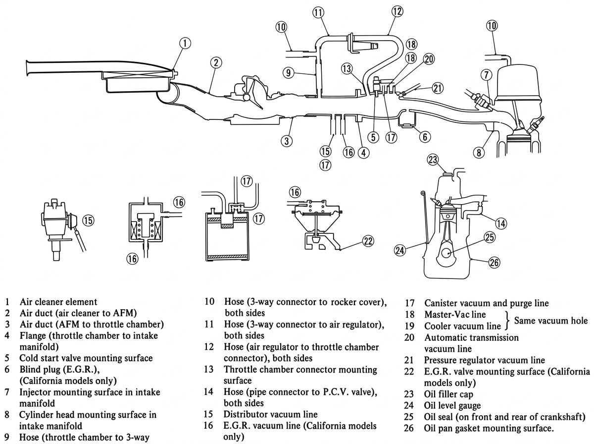
Checking air leakage in air intake system — labeled air-cleaner-to-intake-manifold component diagram referenced from Step 2
- Fuel Pump-Pressure Regulator Operation:
- Pull Solenoid Lead Off Starter
- Turn Key To "Start" And Listen For Fuel Pump And Pressure Regulator Operation.
Results:
(a) Fuel Pump Runs And Pressure Regulator Buzzes: Go To Step 4 Below.
(b) No Noise: Go To Step 6, Page 33. - Ignition Signal Input:
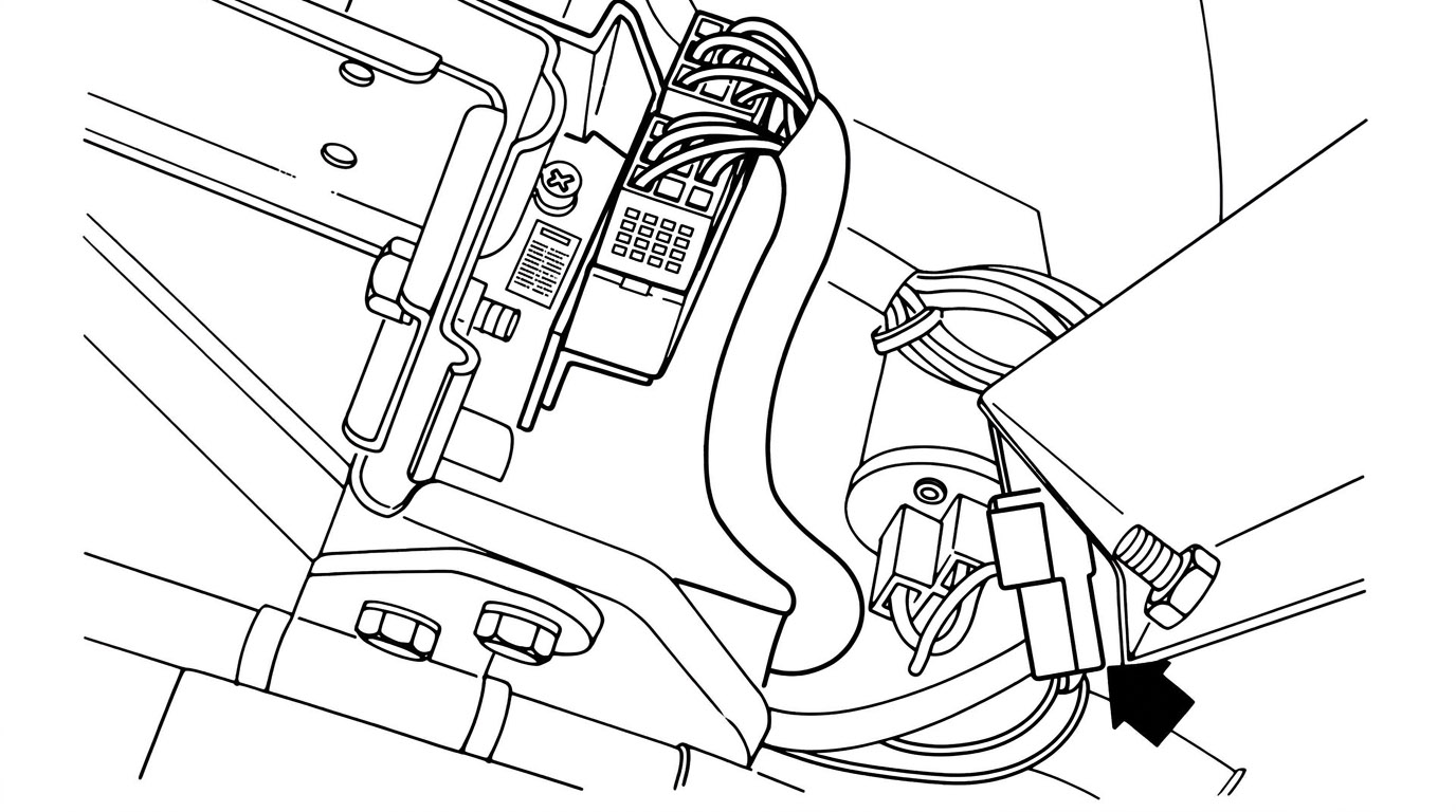
Locating the ignition lead wire to the control unit, next to the power relay
- Locate Ignition Lead Wire To Control Unit (Next To Power Relay-See Drawing).
- Key On Check For Current With Test Light.
Results:
(a) Light On: Go To Step 5, Page 33
(b) Light Off: Check Ignition Circuit, 280-Z Service Manual, page EF-39. - Power Relay - Control Unit - Injector Test:
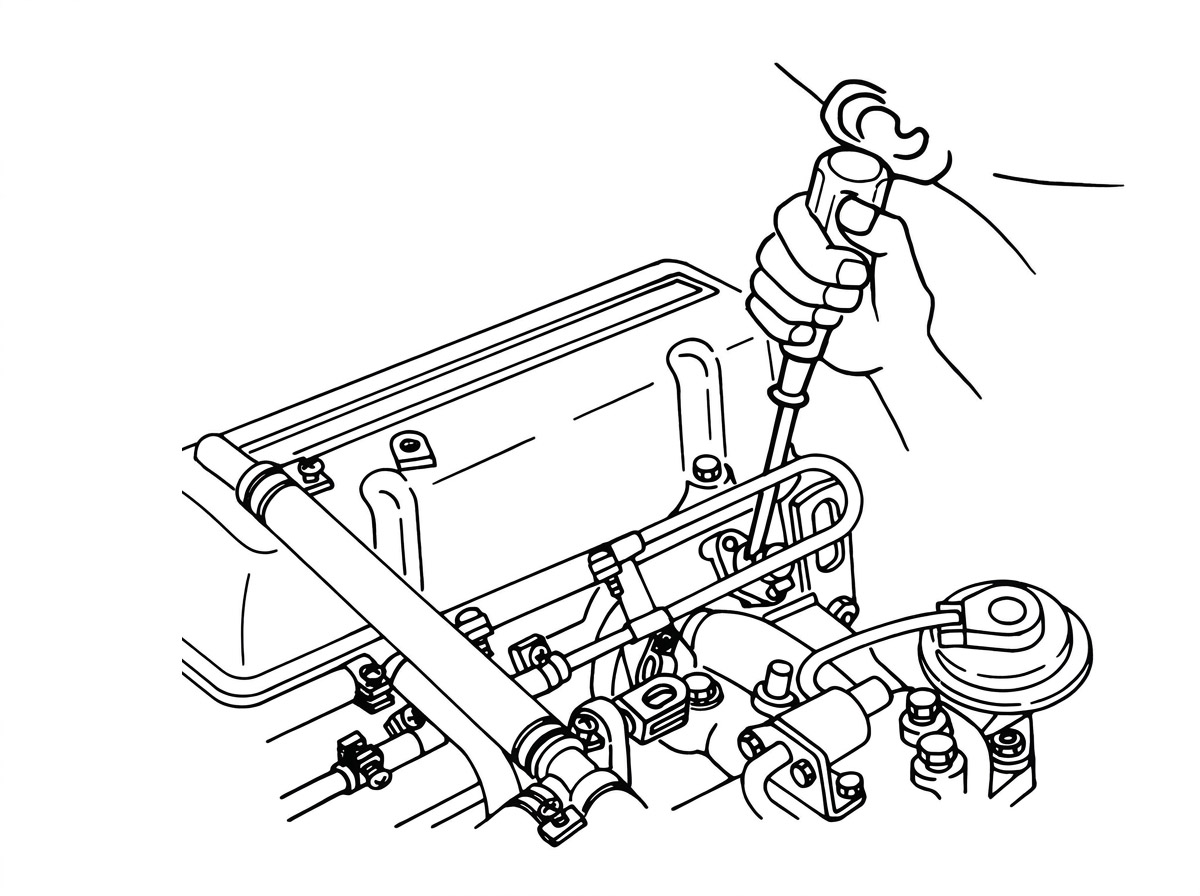
Disconnecting and reconnecting the ignition lead wire at the injector rail to listen for injector clicks
- Key On, Disconnect And Reconnect Ignition Lead Wire Several Times. Have Someone Listen To Each Injector.
Results:
(a) Injectors Click Every Third Break: Perform The Following Circuit Checks At The 35-Pin Connector In The Order Below:
(1) 1 - (6), page 54 (4) 1 - (5), page 53
(2) 1 - (3a - 3c), pages 49 - 51 (5) 3 - (1), page 69
(3) 3 - (3), page 71 (6) 3 - (2), page 70Then, proceed to "Component Checks", page 72.
(b) Injectors Do Not Click: Go To Step 6, Below.
- Power Relay Check:
- Locate Power Relay (Upper Left Hand Kick Panel), Place Your Hand Over It.
- Turn Key First To "On" And Then To "Start".
Results:
(a) Relay Doesn't Click: Perform The Following Circuit Checks In The Order Below:
(1) 3 - (1), page 69 (3) 1 - (8), page 56
(2) 1 - (7), page 55(b) Relay Clicks: Perform The Following Circuit Checks In The Order Below:
(1) 2 - (2), page 62 (3) 1 - (9a - 9d), pages 57 - 60
(2) 2 - (1), page 61 (4) 2 - (3a - 3f), pages 63 - 68If Problem Persists, Reconnect Harness To ECU And Perform Step 5 Again. If Test Still Negative, Try Another Control Unit.
Engine Hard To Start Only When Cold
- Battery Cranking Voltage Check:
- Connect Voltmeter To Battery
- Pull Coil Wire And Ground It
- Crank Engine
Results:
(a) Below 9.6 Volts: Recharge Battery Or Check Ignition Circuit
(b) Above 9.6 Volts: Go To Step 2, Below - Perform The Following Tests:
(1) Circuit Check 3 - (3), page 71
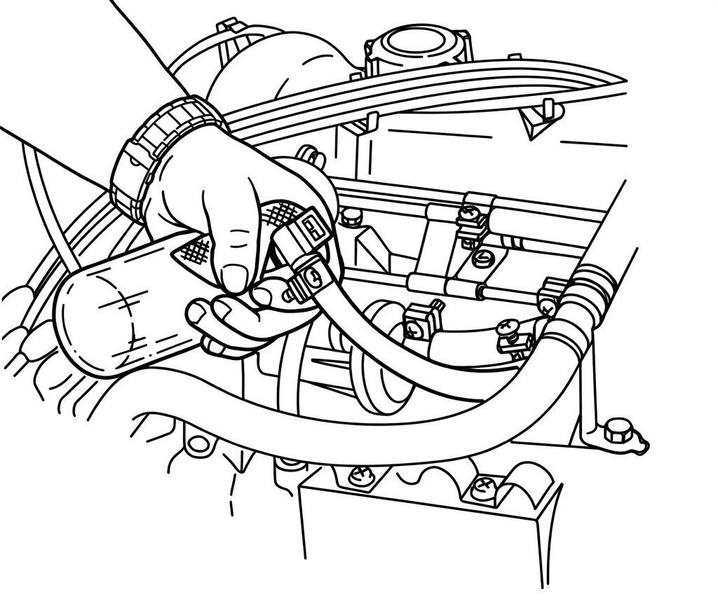
Disconnecting the cold start valve connector for testing
(2) Component Test: Cold Start Valve (280Z Service Manual, page EF-54)
If Both These Tests Are Satisfactory, Proceed To "Engine Will Not Start" On Page 32.
Engine Hard To Start Only When Hot (Above 170°F)
- Check Valve Adjustment, Ignition And Emission Systems
- Cold Start System Test (a)
- Disconnect Cold Start Valve
- Unplug Coil Wire, Ground It
- Crank Engine A Few Times To Clean Out Excess Fuel
- Reconnect Coil Wire And Try To Start Engine
Results:
(a) Engine Starts Easily: Go To Step 3, Below
(b) Engine Still Hard To Start: Perform The Following Checks In The Order Below:
(1) Circuit Test 1 - (6), page 54
(2) Circuit Tests 1 - (3a - 3c), pages 49 - 51
(3) Component Test: Fuel Pressure, 280Z Service Manual, Page EF-56
(4) Component Test: Injectors, 280Z Service Manual, Page EF-57If No Problem Is Found, Proceed To "Engine Will Not Start" On Page 32.
- Cold Start System Test (b)
- Reconnect Cold Start Valve
- Disconnect Thermotime Switch
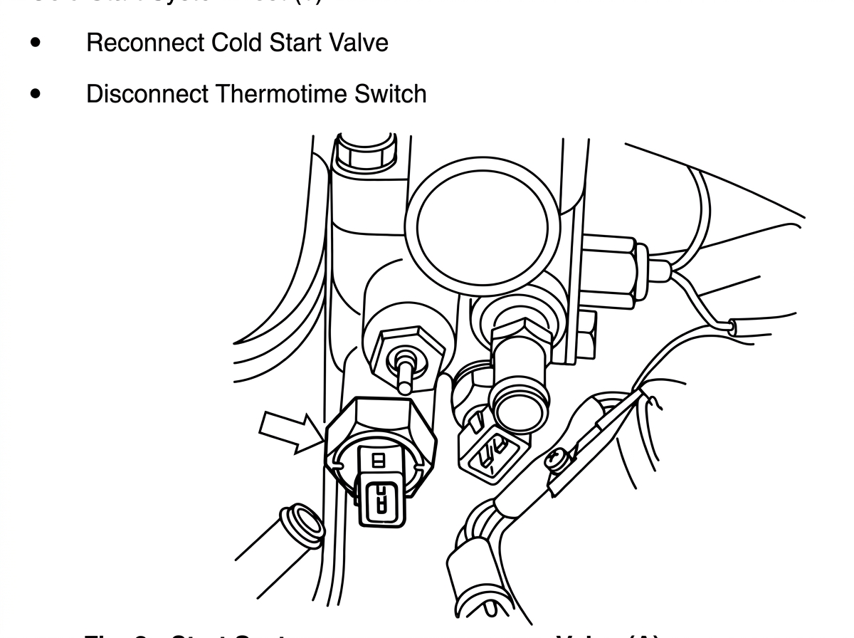
Disconnecting the thermotime switch connector
- Try To Start Engine
Results:
(a) Engine Hard To Start: Check Cold Start Valve (280-Z Service Manual, Page EF-54) And Replace If Necessary.
(b) Engine Starts Easily: Check Thermotime Switch (280Z Service Manual, Page EF-53) And Replace If Necessary
Engine Starts, Then Stalls
- Ignition Signal Input:
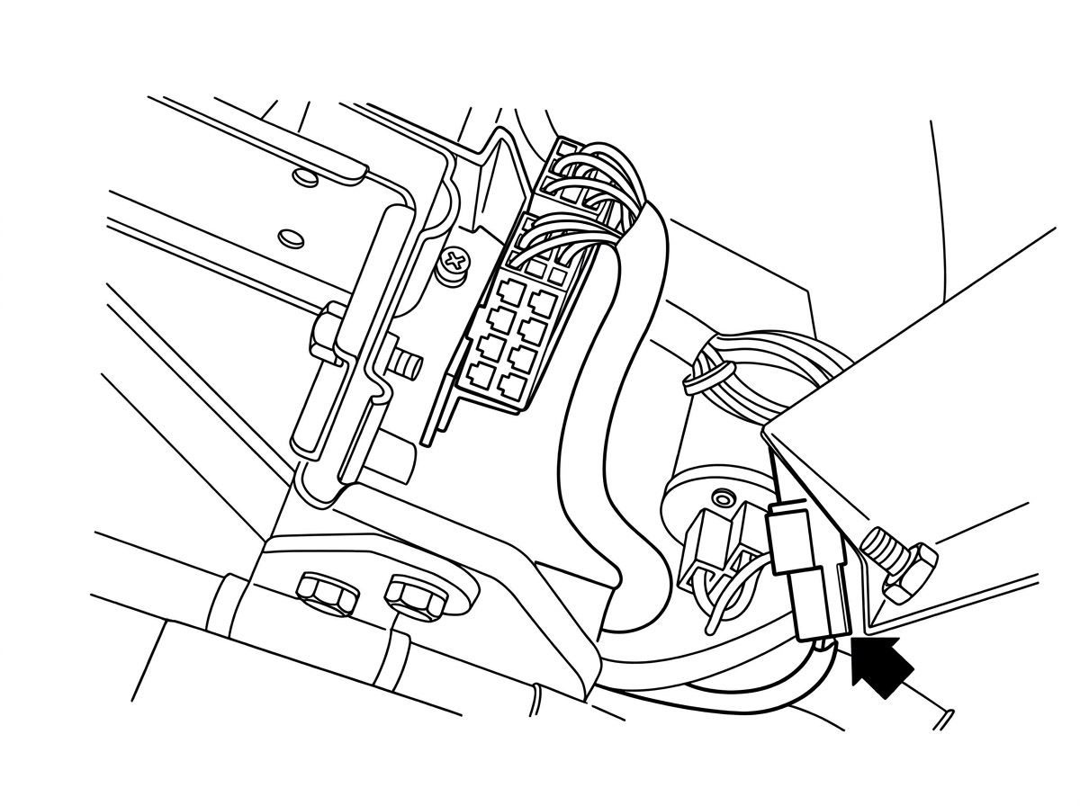
Locating the ignition lead wire to the control unit
- Locate Ignition Lead Wire To Control Unit
- Key On, Check For Current With Test Light
Results:
(a) Light On: Go To Step 2, Below
(b) Light Off: Check Ignition Circuit, 280Z Service Manual, Page EF-39 - Power Relay - Control Unit - Injector Test:
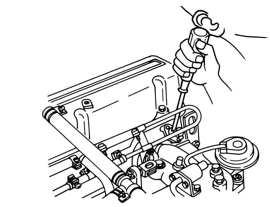
Disconnecting and reconnecting the ignition lead wire at the injector rail to listen for injector clicks
- Key On, Disconnect And Reconnect Ignition Lead Wire Several Times. Have Someone Listen To Each Injector.
Results:
(a) Injectors Click Every Third Break: Go To Step 4, Below
(b) Injectors Don't Click: Go To Step 3, Below - Power Relay Check:
- Locate Power Relay (Upper Left Hand Kick Panel), Place Your Hand Over It
- Turn Key First To "On" And Then To "Start"
Results:
(a) Relay Clicks Twice: Go To Step 4, Below
(b) Relay Clicks Only Once Or Not At All: Perform The Following Circuit Tests In The Order Below:(1) 3 - (1), Page 69 (3) 1 - (8), Page 56
(2) 1 - (7), Page 55 - Air Flow Meter Pump Contacts:
- Remove Front Hose To Air Flow Meter
- Ignition "On"
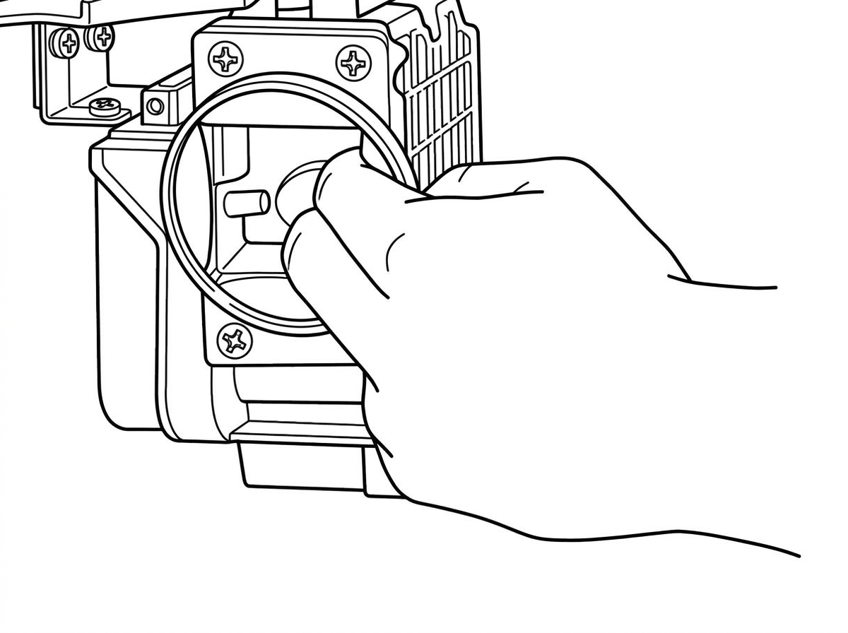
Reaching into the air flow meter to push open the flap and check the fuel pump contacts
- Using A Finger, Reach In And Push Open The Air Flow Meter Flap
Results:
(a) Fuel Pump Operates: Go To Step 5, Below
(b) Fuel Pump Does Not Operate: Check Circuit Outlined In 280-Z Service Manual Page EF-31 - Perform Circuit Test 1 - (6), Page 54
- Check Auxiliary Air Regulator, See 1975 280-Z Service Manual, Page EF-58
If No Problem Found, Proceed To "Engine Will Not Start" On Page 32.
Engine Idles Too Fast — Cannot Be Adjusted With Speed Screw Or Engine Idle Is Unstable
- Unstable Idling: Check Valve Adjustment
- Check That Throttle Plate Is Closing When Throttle Is Released
- Check That EGR Valve Is Not Sticking Open (California Only)
- Check That B.C.D.D. Valve Is Not Open At Idle And That Relief Solenoid Is Connected
- Auxiliary Air Regulator Check:
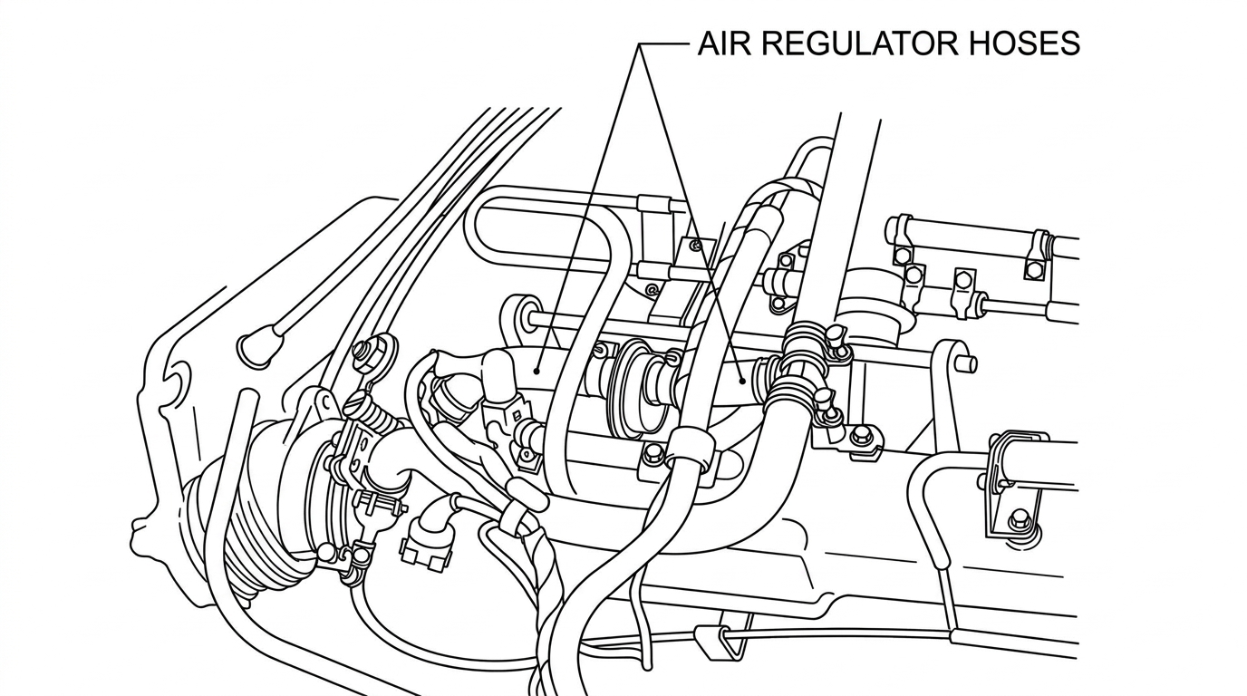
Air regulator hoses at the auxiliary air regulator
- Using Pliers, Pinch Off Hose To Auxiliary Air Regulator
Results:
(a) Idle Drops: Perform Circuit Test 1-(8), Pg. 56. If No Fault Found, Replace Regulator.
(b) Idle Remains High Or Unstable: Go To Step 6, Below - Check For Manifold Vacuum Leaks, Including At PCV Valve, Dip Stick And Oil Filler Cap Seals. (See Diagram Page 31.)
If No Problem Found, Perform The Following Circuit Tests In The Order Below:
(1) 1 - (1), Page 47 (7) 1 - (5), Page 53
(2) 1 - (2), Page 48 (8) 1 - (8), Page 56
(3) 1 - (4), Page 52 (9) 3 - (2), Page 70
(4) 1 - (6), Page 54 (10) 2 - (1), Page 61
(5) 1 - (9a - 9d), Page 57 - 60 (11) 2 - (2), Page 62
(6) 1 - (3a - 3c), Page 49 - 51 (12) 2 - (3a - 3f), Page 63 - 68Then proceed to Component Checks, Page 72.
Engine Misfires — HC Reading Too High
- Check Ignition Circuit Thoroughly
- Check Charging System Voltage Regulator Setting
- Pull All Fuel Injection Connectors Apart And Check For Looseness And Corrosion (Including Ground Circuits). Don't Forget Ignition Input Lead.
- Check Fuel Circuit For Blockage:
- Tank Strainer
- Fuel Filter
- Injectors
- Lines
- Tap Control Unit While Driving To See If This Aggravates Or Alleviates The Problem. If So, Try Another ECU.
- Perform Fuel Pressure Test. 280Z Service Manual, Page EF-57
- Perform All Circuit Tests Starting On Page 45
- Perform Component Tests. See Page 72
Engine Will Not Rev. — Lack Of Power
- Check Transistor Ignition Thoroughly, Including Pickup Coil(s) And Ignition Coil (See Engine Performance And Emission Analysis)
- Make Sure Throttle Plate Is Opening Fully When Accelerator Is Fully Depressed
- Check Air Flow Meter Mechanical Movement:
- Remove Front (Intake Hose)
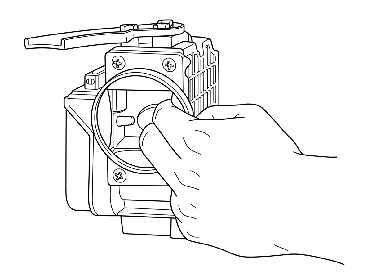
Checking the air flow meter flap for smooth, full mechanical movement
- Using A Finger, Push The Flap Open, Checking That It Opens Smoothly And Fully
- Check For Blockage In Fuel Circuit:
- Tank Strainer
- Fuel Filter
- Lines
- Perform Fuel Pressure Test, 280-Z Service Manual, Page EF-57
- Perform The Following Circuit Tests In The Order Below:
(1) 1 - (2), Page 48 (6) 1 - (1), Page 47
(2) 2 - (1), Page 61 (7) 1 - (4), Page 52
(3) 2 - (2), Page 62 (8) 1 - (6), Page 54
(4) 2 - (3a - 3f), Page 63 - 68 (9) 1 - (8), Page 56
(5) 1 - (3a - 3c), Page 49 - 51 - Perform Component Tests. See Page 72
Hesitation — Stumble On Acceleration
- Check Ignition System Thoroughly. (See Engine Performance And Emission Analysis.)
- Air Flow Meter Mechanical Check:
- Remove Front (Intake) Hose From Air Flow Meter
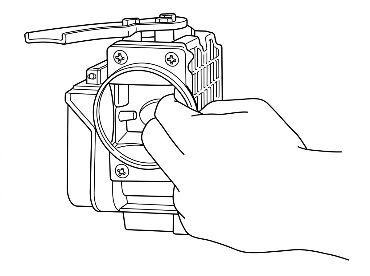
Checking the air flow meter flap for smooth movement and resistance points
- Using A Finger, Check For Smooth Flap Movement
Results:
(a) Resistance Points Felt: Replace Air Flow Meter
(b) Movement Is Normal: Go To Step 3, Below - Check For Intake Manifold Leaks (See Diagram Page 31).
- PCV Valve
- Dip Stick And Oil Filler Cap Seals
- Manifold Gaskets
- Air Flow Meter Hoses
- Perform Fuel Pressure Test, 280-Z Service Manual, Page EF-57
- Perform Complete Circuit Test, Starting On Page 45
- Perform Component Checks, See Page 72
Poor Gas Mileage, Or CO Reading Too High
- Check Timing; Check Ignition System For "Hot" Spark (Use Scope If Available).
- Check Air Cleaner Element
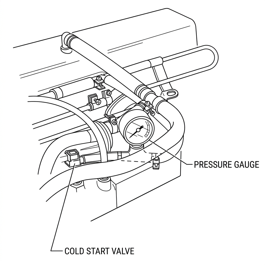
Fuel pressure gauge connected at the cold start valve fitting
- Perform Fuel Pressure Test: See 280Z Service Manual, Page EF-57
- Perform The Following Circuit Tests In The Order Below:
(1) 1 - (6), Page 54 (5) 1 - (3a - 3c), Pages 49 - 51
(2) 1 - (4), Page 52 (6) 3 - (2), Page 70
(3) 1 - (1), Page 47 (7) 1 - (8), Page 56
(4) 1 - (2), Page 48 (8) 2 - (3a - 3f), Pages 63 - 68 - Then Proceed To Component Checks, See Page 72
Surge
- Air Flow Meter Mechanical Check:
- Remove Front (Intake) Air Hose From Air Flow Meter
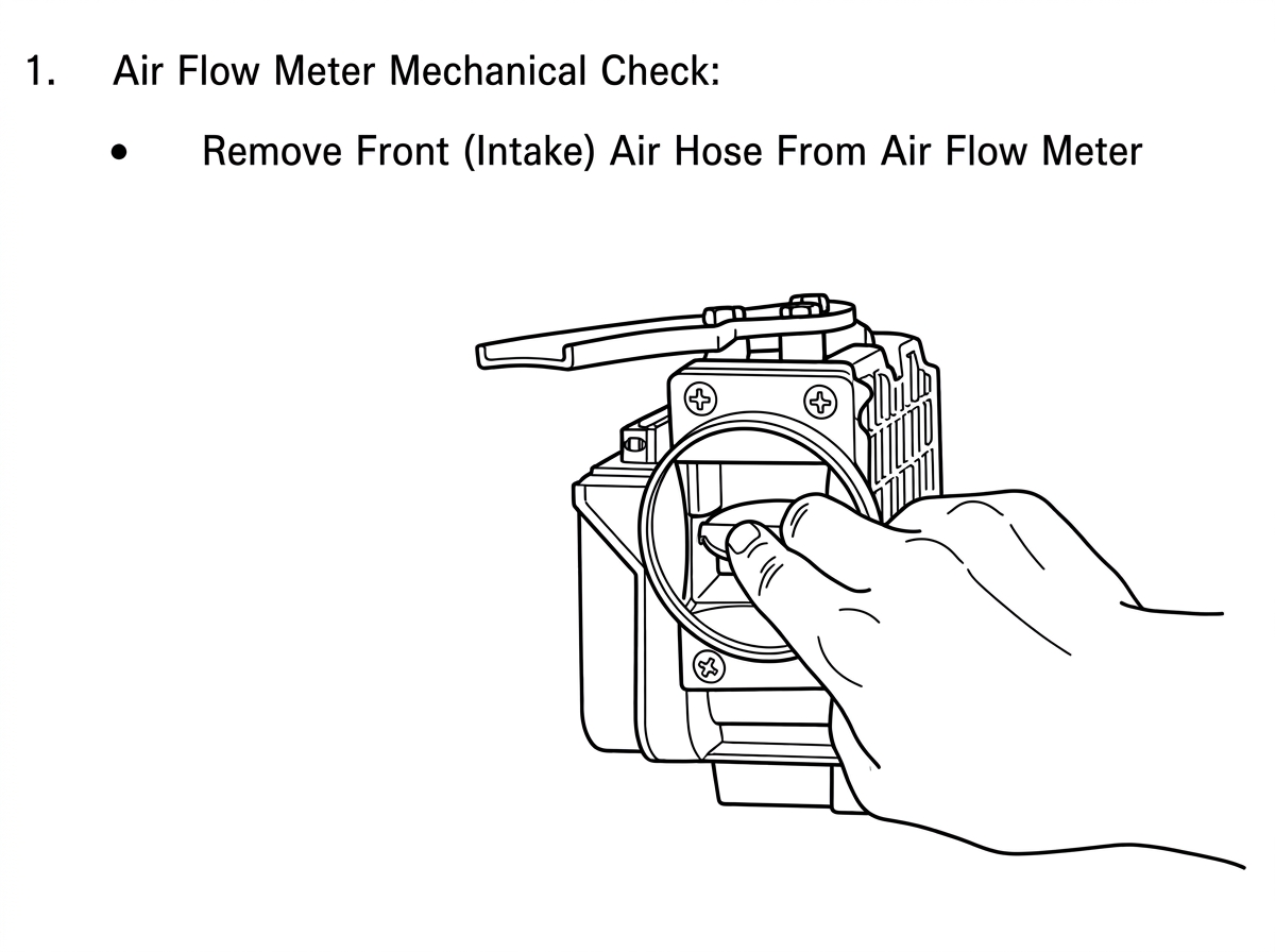
Checking air flow meter flap movement for smoothness of operation
- Using A Finger, Check Flap Movement For Smoothness Of Operation. If No Resistance Is Felt, Go To Step 2 Below.
- Check For Manifold Vacuum Leaks (See Diagram Page 31).
- PCV Valve
- Dip Stick And Oil Filler Cap Seals
- Manifold Gaskets
- Air Flow Meter Hoses
- Perform The Following Circuit Tests In The Order Below:
(1) 1 - (1), Page 47 (7) 1 - (6), Page 54
(2) 1 - (2), Page 48 (8) 1 - (8), Page 56
(3) 1 - (3a - 3c), Pages 49 - 51 (9) 2 - (1), Page 61
(4) 1 - (5), Page 53 (10) 2 - (2), Page 62
(5) 1 - (9a - 9d), Pages 57 - 60 (11) 2 - (3a - 3f), Pages 63 - 68
(6) 1 - (4), Page 52 - Then Proceed To Component Tests, Page 72
Backfiring
- Check For Manifold Vacuum Leaks. (See Diagram Page 31).
- PCV Valve
- Dip Stick And Oil Filler Cap Seals
- Manifold Gaskets
- Air Flow Meter Hoses
- Perform The Following Circuit Tests In The Order Listed:
(1) 1 - (1), Page 47 (5) 1 - (6), Page 54
(2) 1 - (2), Page 48 (6) 2 - (1), Page 61
(3) 1 - (3a - 3c), Pages 49 - 51 (7) 2 - (2), Page 62
(4) 1 - (4), Page 52 (8) 2 - (3a - 3f), Pages 63 - 68 - Then Proceed To The Component Tests On Page 72.
Afterfire Or Afterburning
- Perform The Following Circuit Tests In The Order Listed:
(1) 1 - (1), Page 47 (5) 1 - (6), Page 54
(2) 1 - (2), Page 48 (6) 2 - (3a - 3f), Pages 63 - 68
(3) 1 - (3a - 3c), Pages 49 - 51 (7) 3 - (1), Page 69
(4) 1 - (4), Page 52 - Then Proceed To Component Checks, Page 72
Circuit Testing
Using The 35-Pin Control Unit Connector
| Test # | Description |
|---|---|
| 1 - (1) | Idle Throttle Switch |
| 1 - (2) | Full Throttle Switch |
| 1 - (3a) | Air Flow Meter - Resistance #1 |
| 1 - (3b) | Air Flow Meter - Resistance #2 |
| 1 - (3c) | Air Flow Meter - Resistance #3 |
| 1 - (4) | Air Temperature Sensor Resistance |
| 1 - (5) | Air Flow Meter Fuel Pump Contacts |
| 1 - (6) | Water Temperature Sensor Resistance |
| 1 - (7) | Fuel Pump Relay Circuit |
| 1 - (8) | Air Regulator And Fuel Pump Circuit |
| 1 - (9a) | Control Unit Ground Circuit #1 |
| 1 - (9b) | Control Unit Ground Circuit #2 |
| 1 - (9c) | Control Unit Ground Circuit #3 |
| 1 - (9d) | Control Unit Ground Circuit #4 |
| 2 - (1) | Ignition Coil Trigger Input Circuit |
| 2 - (2) | Control Unit Power Input Circuit |
| 2 - (3a) | #4 Injector Circuit |
| 2 - (3b) | #1 Injector Circuit |
| 2 - (3c) | #5 Injector Circuit |
| 2 - (3d) | #6 Injector Circuit |
| 2 - (3e) | #3 Injector Circuit |
| 2 - (3f) | #2 Injector Circuit |
| 3 - (1) | "Start" Signal Circuit |
| 3 - (2) | Air Regulator Circuit |
| 3 - (3) | Cold Start System Circuit |
| — | Component Checks |
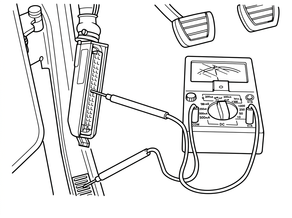
Connecting a multimeter to the 35-pin control unit connector in the driver's footwell for circuit testing
Circuit Testing — 35-Pin Connector Tests
The following tests check continuity, resistance, and voltage at the 35-pin control unit connector for each circuit. Before beginning, turn off the ignition and disconnect the control unit. For each test, identify the pin(s) shown on the connector diagram, connect the tester as specified, and compare the reading to the "Should Read" value. If a test is unsatisfactory, check the referenced component or wiring section.
Test #1
Test #1 – (1): Idle Throttle Switch
Note: Turn off ignition before disconnecting control unit.
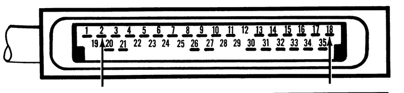
Connector pinout — idle throttle switch test, pins 2 and 18.
| Tester | Leads To Pins | Notes | Should Read |
|---|---|---|---|
| Ohmmeter | 2 – 18 | Throttle Released | Continuity |
| Throttle Depressed | No Continuity |
If test is unsatisfactory, check: 1. Throttle Valve Switch (1975 280Z Service Manual p. EF-56*); 2. Wiring (p. EF-25). *Adjustment of Throttle Valve Switch: See page EF-65.
Test #1 – (2): Full Throttle Switch
Note: Turn off ignition before disconnecting control unit.
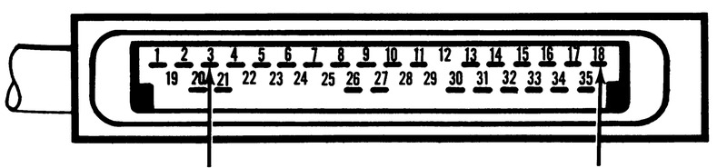
Connector pinout — full throttle switch test, pins 3 and 18.
| Tester | Leads To Pins | Notes | Should Read |
|---|---|---|---|
| Ohmmeter | 3 – 18 | Part Throttle | No Continuity |
| Full Throttle | Continuity |
If test is unsatisfactory, check: 1. Throttle Valve Switch (p. EF-56); 2. Wiring (p. EF-26).
Test #1 – (3a): Air Flow Meter – Resistance #1
Note: Turn off ignition before disconnecting control unit.
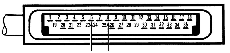
Connector pinout — air flow meter resistance test #1, pins 6 and 8.
| Tester | Leads To Pins | Should Read |
|---|---|---|
| Ohmmeter | 6 – 8 | Approximately 180 Ohms |
If test is unsatisfactory, check: 1. Air Flow Meter (p. EF-51); 2. Wiring (p. EF-27).
Test #1 – (3b): Air Flow Meter – Resistance #2
Note: Turn off ignition before disconnecting control unit.
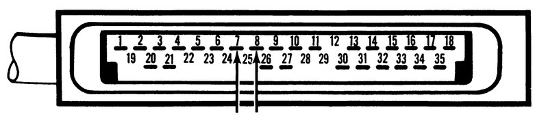
Connector pinout — air flow meter resistance test #2, pins 7 and 8.
| Tester | Leads To Pins | Should Read |
|---|---|---|
| Ohmmeter | 7 – 8 | Continuity (Small Resistance) |
If test is unsatisfactory, check: 1. Air Flow Meter (p. EF-51); 2. Wiring (p. EF-28).
Test #1 – (3c): Air Flow Meter – Resistance #3
Note: Turn off ignition before disconnecting control unit.
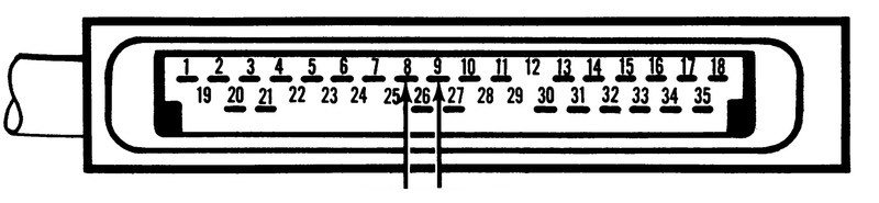
Connector pinout — air flow meter resistance test #3, pins 8 and 9.
| Tester | Leads To Pins | Should Read |
|---|---|---|
| Ohmmeter | 8 – 9 | Approximately 100 Ohms |
If test is unsatisfactory, check: 1. Air Flow Meter (p. EF-51); 2. Wiring (p. EF-29).
Test #1 – (4): Air Temperature Sensor Resistance
Note: Turn off ignition before disconnecting control unit.
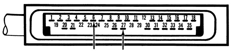
Connector pinout — air temperature sensor resistance test, pins 6 and 27.
| Tester | Leads To Pins | Air Intake Temperature | Should Read |
|---|---|---|---|
| Ohmmeter | 6 – 27 | -14° | 7600 – 10,800 Ohms |
| 50° | 3250 – 4150 Ohms | ||
| 68° | 2250 – 2750 Ohms | ||
| 122° | 740 – 940 Ohms | ||
| 176° | 290 – 360 Ohms |
If test is unsatisfactory, check: 1. Air Temperature Sensor (p. EF-52); 2. Wiring (p. EF-30).
Test #1 – (5): Air Flow Meter Fuel Pump Contacts
Note: Turn off ignition before disconnecting control unit.
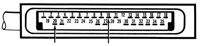
Connector pinout — air flow meter fuel pump contacts test, pins 10 and 20.
| Tester | Leads To Pins | Notes | Should Read |
|---|---|---|---|
| Ohmmeter | 10 – 20 | Air Flow Meter Flap At Rest | No Continuity |
| Air Flow Meter Flap Pushed Open | Continuity |
If test is unsatisfactory, check: 1. Fuel Pump Contact Points (p. EF-52); 2. Wiring (p. EF-31).
Test #1 – (6): Water Temperature Sensor Resistance
Note: Turn off ignition before disconnecting control unit.
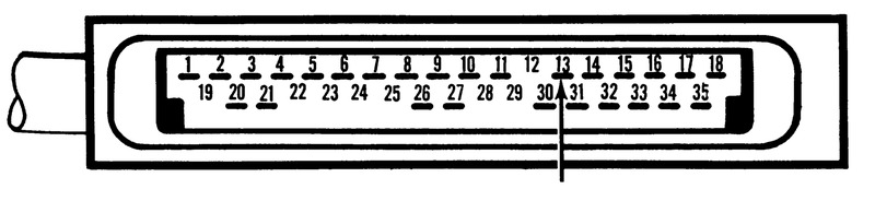
Connector pinout — water temperature sensor resistance test, pin 13 to vehicle ground.
| Tester | Leads To Pins | Engine Coolant Temperature | Should Read |
|---|---|---|---|
| Ohmmeter | 13 – Vehicle Ground | -18° | 7600 – 10,800 Ohms |
| 50° | 3250 – 4150 Ohms | ||
| 68° | 2250 – 2750 Ohms | ||
| 122° | 740 – 940 Ohms | ||
| 176° | 290 – 360 Ohms |
If test is unsatisfactory, check: 1. Water Temperature Sensor (p. EF-52, 53); 2. Wiring (p. EF-32).
Test #1 – (7): Fuel Pump Relay Circuit
Note: Turn off ignition before disconnecting control unit.
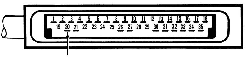
Connector pinout — fuel pump relay circuit test, pin 20 to vehicle ground.
| Tester | Leads To Pins | Should Read |
|---|---|---|
| Ohmmeter | 20 – Vehicle Ground | Continuity |
If test is unsatisfactory, check: 1. Fuel Injection Relay (p. EF-54); 2. Wiring (p. EF-33).
Test #1 – (8): Air Regulator and Fuel Pump Circuit
Note: Turn off ignition before disconnecting control unit.
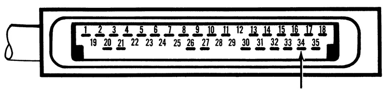
Connector pinout — air regulator and fuel pump circuit test, pin 34 to vehicle ground.
| Tester | Leads To Pins | Should Read |
|---|---|---|
| Ohmmeter | 34 – Vehicle Ground | Continuity |
If test is unsatisfactory, check: 1. Air Regulator (p. EF-58); 2. Fuel Pump (p. EF-56); 3. Wiring (p. EF-34).
Test #1 – 9(a): Control Unit Ground Circuit #1
Note: Turn off ignition before disconnecting control unit.
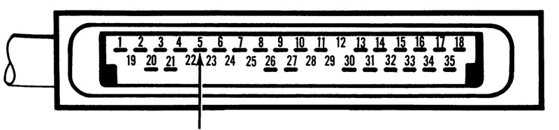
Connector pinout — control unit ground circuit #1 test, pin 5 to vehicle ground.
| Tester | Leads To Pins | Should Read |
|---|---|---|
| Ohmmeter | 5 – Vehicle Ground | Continuity |
If test is unsatisfactory, check: 1. Wiring harness (p. EF-35).
Test #1 – 9(b): Control Unit Ground Circuit #2
Note: Turn off ignition before disconnecting control unit.

Connector pinout — control unit ground circuit #2 test, pin 16 to vehicle ground.
| Tester | Leads To Pins | Should Read |
|---|---|---|
| Ohmmeter | 16 – Vehicle Ground | Continuity |
If test is unsatisfactory, check: 1. Wiring Harness (p. EF-36).
Test #1 – 9(c): Control Unit Ground Circuit #3
Note: Turn off ignition before disconnecting control unit.
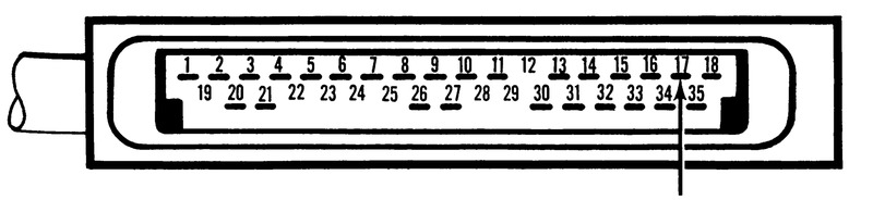
Connector pinout — control unit ground circuit #3 test, pin 17 to vehicle ground.
| Tester | Leads To Pins | Should Read |
|---|---|---|
| Ohmmeter | 17 – Vehicle Ground | Continuity |
If test is unsatisfactory, check: 1. Wiring Harness (p. EF-37).
Test #1 – 9(d): Control Unit Ground Circuit #4
Note: Turn off ignition before disconnecting control unit.
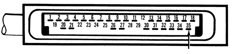
Connector pinout — control unit ground circuit #4 test, pin 35 to vehicle ground.
| Tester | Leads To Pins | Should Read |
|---|---|---|
| Ohmmeter | 35 – Vehicle Ground | Continuity |
If test is unsatisfactory, check: 1. Wiring Harness (p. EF-38).
Test #2
Test #2 – (1): Ignition Coil Trigger Input Circuit
Note: Turn off ignition before disconnecting control unit.
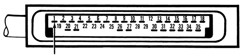
Connector pinout — ignition coil trigger input circuit test, pin 1 to vehicle ground.
| Tester | Leads To Pins (+/-) | Notes | Should Read |
|---|---|---|---|
| Voltmeter | 1 (+), Vehicle Ground (-) | Ignition "On" | Battery Voltage |
If test is unsatisfactory, check: 1. Ignition Input Circuit (p. EF-39); 2. In-Line Harness Connector (p. EF-40).
Test #2 – (2): Control Unit Power Input Circuit
Note: Turn off ignition before disconnecting control unit.
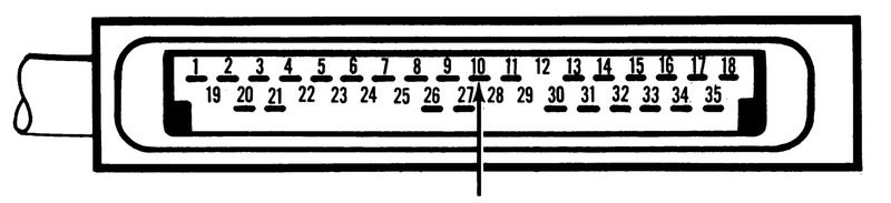
Connector pinout — control unit power input circuit test, pin 10 to vehicle ground.
| Tester | Leads To Pins (+/-) | Notes | Should Read |
|---|---|---|---|
| Voltmeter | 10 (+), Vehicle Ground (-) | Ignition "On" | Battery Voltage |
If test is unsatisfactory, check: 1. Power Relay (p. EF-54); 2. Wiring (p. EF-40).
Test #2 – 3(a): #4 Injector Circuit
Note: Turn off ignition before disconnecting control unit.
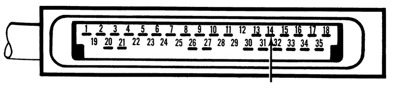
Connector pinout — #4 injector circuit test, pin 14 to vehicle ground.
| Tester | Leads To Pins (+/-) | Notes | Should Read |
|---|---|---|---|
| Voltmeter | 14 (+), Vehicle Ground (-) | Ignition "On" | Battery Voltage |
If test is unsatisfactory, check: 1. Wiring (p. EF-41); 2. Resistor (p. EF-56); 3. Relay (p. EF-54); 4. Injector (p. EF-57).
Test #2 – 3(b): #1 Injector Circuit
Note: Turn off ignition before disconnecting control unit.
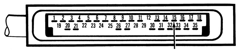
Connector pinout — #1 injector circuit test, pin 15 to vehicle ground.
| Tester | Leads To Pins (+/-) | Notes | Should Read |
|---|---|---|---|
| Voltmeter | 15 (+), Vehicle Ground (-) | Ignition "On" | Battery Voltage |
If test is unsatisfactory, check: 1. Wiring (p. EF-42); 2. Resistor (p. EF-56); 3. Relay (p. EF-54); 4. Injector (p. EF-57).
Test #2 – 3(c): #5 Injector Circuit
Note: Turn off ignition before disconnecting control unit.
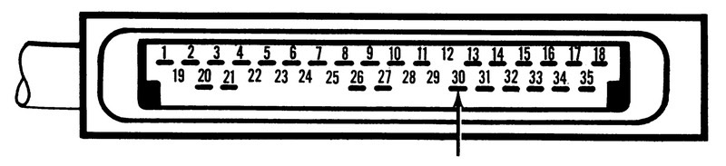
Connector pinout — #5 injector circuit test, pin 30 to vehicle ground.
| Tester | Leads To Pins (+/-) | Notes | Should Read |
|---|---|---|---|
| Voltmeter | 30 (+), Vehicle Ground (-) | Ignition "On" | Battery Voltage |
If test is unsatisfactory, check: 1. Wiring (p. EF-43); 2. Resistor (p. EF-56); 3. Relay (p. EF-54); 4. Injector (p. EF-57).
Test #2 – 3(d): #6 Injector Circuit
Note: Turn off ignition before disconnecting control unit.
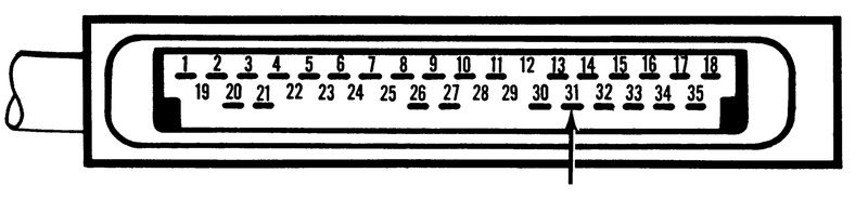
Connector pinout — #6 injector circuit test, pin 31 to vehicle ground.
| Tester | Leads To Pins (+/-) | Notes | Should Read |
|---|---|---|---|
| Voltmeter | 31 (+), Vehicle Ground (-) | Ignition "On" | Battery Voltage |
If test is unsatisfactory, check: 1. Wiring (p. EF-44); 2. Resistor (p. EF-56); 3. Relay (p. EF-54); 4. Injector (p. EF-57).
Test #2 – 3(e): #3 Injector Circuit
Note: Turn off ignition before disconnecting control unit.
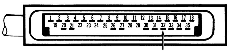
Connector pinout — #3 injector circuit test, pin 32 to vehicle ground.
| Tester | Leads To Pins (+/-) | Notes | Should Read |
|---|---|---|---|
| Voltmeter | 32 (+), Vehicle Ground (-) | Ignition "On" | Battery Voltage |
If test is unsatisfactory, check: 1. Wiring (p. EF-45); 2. Resistor (p. EF-50); 3. Relay (p. EF-54); 4. Injector (p. EF-57).
Test #2 – 3(f): #2 Injector Circuit
Note: Turn off ignition before disconnecting control unit.
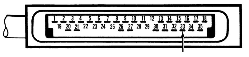
Connector pinout — #2 injector circuit test, pin 33 to vehicle ground.
| Tester | Leads To Pins (+/-) | Notes | Should Read |
|---|---|---|---|
| Voltmeter | 33 (+), Vehicle Ground (-) | Ignition "On" | Battery Voltage |
If test is unsatisfactory, check: 1. Wiring (p. EF-46); 2. Resistor (p. EF-56); 3. Relay (p. EF-54); 4. Injector (p. EF-57).
Test #3
Test #3 – (1): "Start" Signal Circuit
Note: Turn off ignition before disconnecting control unit.
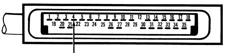
Connector pinout — "start" signal circuit test, pin 4 to vehicle ground.
| Tester | Leads To Pins (+/-) | Notes | Should Read |
|---|---|---|---|
| Voltmeter | 4 (+), Vehicle Ground (-) | 1. Starter solenoid lead disconnected 2. Disconnect cold start v. 3. Key in "Start" position |
Battery Voltage |
If test is unsatisfactory, check: 1. Wiring (p. EF-47).
Test #3 – (2): Air Regulator Circuit
Note: Turn off ignition before disconnecting control unit.
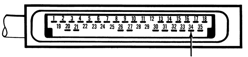
Connector pinout — air regulator circuit test, pin 34 to vehicle ground.
| Tester | Leads To Pins (+/-) | Notes | Should Read |
|---|---|---|---|
| Voltmeter | 34 (+), Vehicle Ground (-) | 1. Starter solenoid lead wire disconnected 2. Disconnect cold start valve 3. Key in "Start" position |
Battery Voltage |
If test is unsatisfactory, check: 1. Air Regulator (p. EF-58); 2. Wiring (p. EF-48).
Test #3 – (3): Cold Start System Circuit
Note: Turn off ignition before disconnecting control unit.
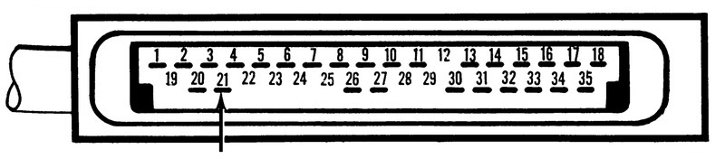
Connector pinout — cold start system circuit test, pin 21 to vehicle ground.
| Tester | Leads To Pins (+/-) | Notes | Should Read |
|---|---|---|---|
| Voltmeter | 21 (+), Vehicle Ground (-) | 1. Engine cold (water temperature below 100 degrees) 2. Starter solenoid lead wire disconnected 3. Key to "start" position |
Little or no voltage at first; then battery voltage after no more than 15 sec. |
If test is unsatisfactory, check: 1. Cold Start Valve (p. EF-54); 2. Thermotime Switch (p. EF-53); 3. Relay (p. EF-54); 4. Wiring (p. EF-49).
Component Checks
To be performed only after circuit tests are completed. Page references are to the 1975 280Z Service Manual.
Engine Will Not Start
- Injector Sound (p. EF-57)
- Relay (p. EF-54)
- Control Unit Replacement (p. EF-51)
- Air Flow Meter Flap Operation (p. EF-51)
- Air Flow Meter Resistance/Voltage Meas. (p. EF-52)
- Fuel Pressure Test (p. EF-56/7)
- Injector Leakage (p. EF-57)
- Cold Start Valve Leakage (p. EF-54)
- Pressure Regulator (p. EF-57)
Idle Too High Or Too Rough
- Injector Sound (p. EF-57)
- Fuel Pressure Test (p. EF-56/7)
- Injector Leakage (p. EF-57)
- Cold Start Valve Leakage (p. EF-54)
- Pressure Regulator (p. EF-57)
Engine Misfires — HC Reading Too High
- Injector Sound (p. EF-57)
- Auxiliary Air Regulator (p. EF-58)
- Control Unit Replacement (p. EF-51)
- Air Flow Meter Flap Operation (p. EF-51)
- Air Flow Meter Resistance/Voltage Meas. (p. EF-52)
- Fuel Pressure Test (p. EF-56/7)
- Pressure Regulator (p. EF-57)
Lack Of Power — Engine Will Not Rev.
- Injector Sound (p. EF-57)
- Air Flow Meter Flap Operation (p. EF-51)
- Air Flow Meter Resistance/Voltage Meas. (p. EF-52)
- Fuel Pressure Test (p. EF-56/7)
- Injector Leakage (p. EF-57)
- Cold Start Valve Leakage (p. EF-54)
- Pressure Regulator (p. EF-57)
Hesitation — Stumble
- Control Unit Replacement (p. EF-51)
- Air Flow Meter Resistance/Voltage Meas. (p. EF-52)
- Fuel Pressure Test (p. EF-56/7)
- Injector Leakage (p. EF-57)
- Pressure Regulator (p. EF-57)
Poor Gas Mileage, Or CO Too High
- Cold Start Valve (p. EF-54)
- Control Unit Replacement (p. EF-51)
- Air Flow Meter Flap Operation (p. EF-51)
- Air Flow Meter Resistance/Voltage Meas. (p. EF-52)
- Fuel Pressure Test (p. EF-56/7)
- Cold Start Valve Leakage (p. EF-54)
- Pressure Regulator (p. EF-57)
Engine Surges
- Auxiliary Air Regulator (p. EF-58)
- Control Unit Replacement (p. EF-51)
- Air Flow Meter Flap Operation (p. EF-51)
- Air Flow Meter Resistance/Voltage Meas. (p. EF-52)
- Fuel Pressure Test (p. EF-56/7)
- Injector Leakage (p. EF-57)
- Cold Start Valve Leakage (p. EF-54)
Backfiring
- Control Unit Replacement (p. EF-51)
- Air Flow Meter Flap Operation (p. EF-51)
- Air Flow Meter Resistance/Voltage Meas. (p. EF-52)
- Fuel Pressure Test (p. EF-56/7)
Afterburning
- Control Unit Replacement (p. EF-51)
- Air Flow Meter Flap Operation (p. EF-51)
- Air Flow Meter Resistance/Voltage Meas. (p. EF-52)
- Fuel Pressure Test (p. EF-56/7)